We know that the most traditional light control circuit is controlled by a CdS (cadmium sulfide) photoresistor as a sensor. However, there are some problems in CdS, such as complicated application circuit, occupying large PCB space and wasting man-hours; the cadmium sulfide raw materials used are not environmentally friendly; the light threshold (sensitivity) of the device is difficult to adjust, and the low illumination does not respond; the dispersion is large, a batch If the big goods are made, the sensitivity of each one may be different; the performance is unstable, and after a period of time, its light resistance and dark resistance will deviate from the original parameters.
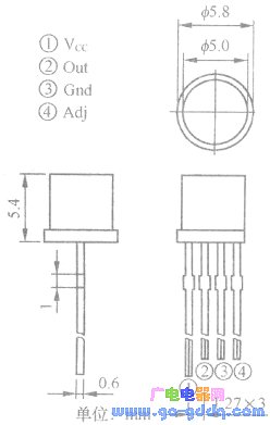
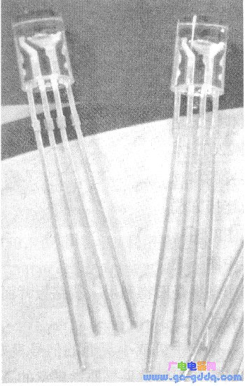
This article introduces the new visible light controller ON9668, which integrates dual-light sensitive element + amplification + logic + switch + power drive function. It basically outputs high and low level without external circuits, and the output current is up to 30mA. Directly drive LEDs, incandescent lamps, relays. The package is shown in the figure above, and the actual object is shown below. Among them, Adj foot is the external light valve value adjustment, after the user sets the required light threshold value, only one resistor is needed, the IC itself has good consistency, and it is not necessary to adjust each. The special feature of the receiving spectrum is that the main and auxiliary dual sensitive elements are used inside the chip. The main sensitive element A is a full-wave sensitive element, and the secondary sensitive element B is an infrared sensitive element. Using the difference amplification (AB), the similarity is obtained. The visible light signal of the human eye effectively solves the influence of infrared light. Its typical incident value is at 520 nm, while the phototransistor is at 850 nm.
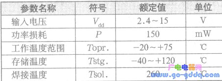
The basic electrical parameters of the ON9668 are shown below.
The internal logic of ON9668 is set to 20% illuminance hysteresis, which can prevent the output jump of the point near the light threshold, corresponding to the voltage of Adj pin 1.2V-1.6V. The working logic is: when the human illuminance does not reach the set threshold, the Adj pin voltage changes with the light intensity ratio, the Out end maintains the original low level, and the Adj pin voltage reaches 1.2V, the Out end continues to maintain the original low level. When the light continues to increase, the voltage of the Adj pin rises to 1.6V, the Out end changes from a low level to a high level; when the incident light continues to increase, the Adj end will be locked by 1.6V, only the light is strong It becomes weaker. When the voltage of Adj is lower than 1.2V, Out changes from high level to low level. This hysteresis circuit is designed to prevent the output from dimming when the light is at the threshold threshold, effectively solving the stroboscopic problem.
ON9668 can be widely used in outdoor advertising machines, induction lighting appliances, toy manufacturing, and can achieve energy-saving control purposes. It can also be used for instrumentation and industrial control. It can replace traditional photoresistors, photodiodes, phototransistors, and is an environmentally friendly Components. 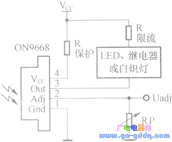
The basic application circuit of ON9668 is shown in the figure above. Let's look at three typical application circuits.
1. Application circuit for light control drive relay
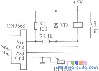
The figure above shows the application circuit of the device for the light-controlled driving relay. Adjusting the resistance of the RP can set the illumination point of the relay action. The larger the resistance value, the lower the threshold value of the light threshold (the resistance of the RP determines Magnification of the internal amplifier of the device). R1 is the protection resistor. The value is generally recommended to be within 100Ω. R2 is the internal pull-up resistor. The human beam is below the set threshold. The Out terminal is low. The relay is in the pull-in state. When the threshold is above the threshold, Out. The terminal is high and the relay is off. Of course, it can also be applied to a person whose light is below the threshold relay disconnection state.
2. Used in light control music circuit
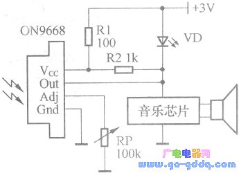
The figure above shows the device applied to a light control music circuit. RP is also the resistor that adjusts the limit of the light valve. When the light received by the device is lower than the set threshold, the Out output is low, the LED indicator VD is on and the music chip is not working. When the light received by the device is higher than the set threshold, Out The output level is high, the music piece is powered to work, and the LED indicator VD is off.
3. For light control lamp circuit
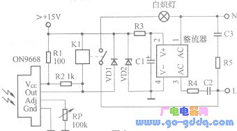
The above figure shows the AC light control lamp circuit made by the device. The adjustment RP is used to determine the light valve point where the light is bright. The circuit works when the light is weak, and the light is not bright when the light is strong. The operating current of the device is very small. When designing the parameters of the RC step-down circuit, the design is at a maximum of 1 mA, and the rest is the working current of the relay. The circuit should pay attention to the personal safety of the non-isolated power supply.
Dock Station Type C,7-Port USB Charging Station Dock,7-Port Charging Station,Type C USB HUB,7 in 1 USB HUB C Docking Station
Shenzhen Konchang Electronic Technology Co.,Ltd , https://www.konchangs.com