Problems between memory and other components are often present on the interfaces between these devices, and these system-level problems are sometimes difficult to detect. This article details a test tool that can easily identify and resolve these problems with memory interfaces, making your design more robust.
In the past, design engineers have used signal integrity (SI) testing in the design of new systems and used to stabilize product quality. Although SI is very valuable in the engineering phase, it is not a panacea. As product design continues to deepen, its value will actually become smaller and smaller, and it will be supplemented or replaced by temperature and voltage margin test (margin tesTIng). SI testing to stabilize product quality.
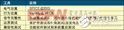
Table 1: Memory design, testing, and verification tools.
Proper selection of tools for memory design, measurement, and verification will reduce engineering time and increase the likelihood of detecting potential problems. Table 1 is a short description of five important tools for memory design. Since this article focuses on tools for validating the functionality and robustness of the design, this list does not fully list all memory design tools. Table 2 shows when it is most effective to use these tools.
5 stages of product development
Debugging labs without logic analyzers is incredible for design and commissioning. However, due to cost and time considerations, logic analyzers are rarely the tool of choice for detecting faults or problems within a system. They are often used for debugging by compatibility or 4-corner test (4-corner) detected problems. Product development consists of five phases:
Stage 1 - Design
To implement a concept or idea in hardware design, because there is no ready-made prototype, only simulation tools can be used. Therefore, design engineers can only rely on electrical and behavioral simulation tools to design.
Stage 2 - Alpha Prototype
The alpha prototype is an initial or earlier prototype that may undergo multiple changes before production (BIOS, functionality, etc.).
The design engineer must perform enough testing on the alpha prototype to ensure that the next prototype, at least from a hardware perspective, will be close to the production ready state. In this regard, reliable tools will be crucial.
The first tools to be used are startup and software verification, which yields valuable information that is combined with basic software inspection to indicate the data that needs to be changed. Due to basic hardware changes, thorough software verification Maybe not yet feasible.
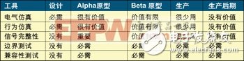
Table 2: Tools to verify memory functionality as opposed to the design phase.
At this stage, the SI test plays an important role in capturing the analog signals on the traces on the board. These captures can be compared to the emulation or device specifications to determine if the device is compliant and has sufficient timing margin. Otherwise, it must be Improve the device.
However, one tool that should not be used at this stage is the marginal test, which can only be used after the hardware is completed. After running the appropriate tests, the design engineer will make a series of design changes, including simulations that may be electrical or behavioral to ensure that the design achieves the desired results.
Stage 3 - Beta Prototype
In the final stage (beta prototype), the hardware is close to the finished state, and only a few minor problems arise. The combined test ensures that the system is in production ready state, and the software or compatibility test must be thorough. This test can be performed separately or with margins. Testing is performed in conjunction, and the coverage of marginal testing should be broad. Different temperatures and their limit voltage levels are valuable in identifying these problems and margins, and this combination should capture possible memory failures.
The SI test has a limited role at this stage, but it can be used to debug functional faults or to confirm changes made during the alpha prototype phase. SI testing should not be used to verify signals or networks from unmodified alpha prototypes. If there are any additional modifications in the beta prototype phase, it is necessary to confirm these modifications by electrical and/or behavioral simulation or SI.
Stage 4 - Production
There are very few changes to the system during the production phase. The focus of this phase is on stabilizing product quality. The production of the system may take months or even years. This production may use hundreds or thousands of components. The company has a set. The process of stabilizing product quality is particularly important.
A series of quality tests on the components after the system enters the production phase ensures adequate component supply so that production is not interrupted. In the production phase, there is very little change in the stitching and layout of the motherboard. Since the SI test has been used to confirm those changes, SI testing is no longer necessary at this stage. In addition, SI testing does not capture failures caused by system/memory related issues. The key to preferred tools and stable product quality is compatibility and marginal testing.
Stage 5 - Post Production
Systems such as MP3 players or DVD recorders do not have the requirement for stable product quality in the later stages of production. However, other systems may have memory upgrade or support requirements, which are especially common in notebook computers, mobile PCs and other devices. And in the latter part of production is important for several years, margin testing and compatibility testing become the key to stable product quality.
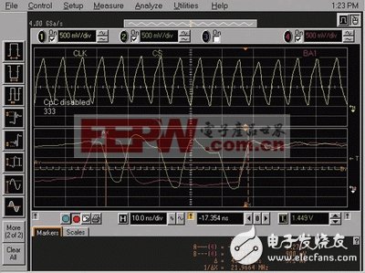
Figure 1: Typical signal integrity issues obtained from an oscilloscope.
Signal integrity test
Electronic design engineers like to use an oscilloscope to observe circuit design and evaluate signals. Figure 1 shows a typical SI capture. In this example, the target photo indicates that the signal is from a single DDR Synchronous Dynamic Random Access Memory (SDRAM) component: address group 1, chip select signal, and different system clocks.
The SI test process uses an oscilloscope light pattern of the system signal to evaluate changes in voltage over time. These light maps or "captures" visually evaluate the violation status. This method is a high demand due to the level of engineering experts and is therefore a waste. The process of time.
The SI test chart shown in Figure 1 can reflect ringing, overshoot/undershoot, and clock collisions (slope, setup/hold time, bus contention, etc.). If any of the above conditions occur, pass compatibility. And marginal testing can easily detect system failures. After these problems are discovered, other tools (logic analyzers, SI tests, etc.) can determine the cause of the failure.
Limitations of SI analysis
SI analysis is becoming more and more difficult and time consuming. In the case of FBGA packages, it is almost impossible to perform SI analysis. What are the reasons? Unless the probe point is added to the design, it is impossible to detect the signal in the FBGA package.
In a multi-chip module (MCM) package, a variety of different chips are combined in a single package that can be protected with either a mold compound or a hermetic method, and signals within the package cannot be detected.
Using a detector to measure SI changes the signal being measured, which can introduce problems or increase the SI change. Although active or field effect transistor (FET) detectors can be employed, this situation is becoming more common due to increased frequency, especially in systems with point-to-point structures.
For memory quality or stable product quality, SI testing has its limitations. Micron has used hundreds of SI oscilloscopes to capture and analyze multiple internal quality tests in memory, drawing the following conclusions:
* SI testing can capture faults and identify major errors early in development.
* SI test is used to verify board changes.
* After the board design is completed, the SI test has a little value.
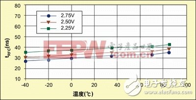
Figure 2: An example of device specifications that vary with voltage and temperature.
Micron's internal test flow has moved away from the SI test, which consists of the following:
* Compatibility and marginal testing is used to confirm or test a system with memory.
* After the compatibility and marginal testing detected an error, different diagnostic tools were used to isolate the failure.
* If the software determines the type of fault (address, row, single unit, etc.) in the system, the memory chip or module is isolated and tested, then we will try to replicate this fault condition in the memory test fixture.
* If the software does not provide details about the fault, remove the memory from the system and perform a component or module test to detect the fault.
* Logic analyzers can be used to identify fault problems/types and violations.
Despite the use of oscilloscopes, experience has shown that other tools can be more effective in quickly measuring, validating, and debugging systems. We believe these alternative tools enable design engineers to quickly troubleshoot and eliminate faults.
Micron's self-quality control process has the following conclusions:
* Regular compatibility testing and marginal testing can expose problems or difficulties in some systems.
* SI cannot find any problems that are not recognized by memory or system level diagnostics. SI finds the same faults as other tests found, thus repeating the performance of marginal and software tests.
* SI testing is time consuming, and it takes time to probe the 64-bit data bus and capture the target oscilloscope screen image.
* SI uses expensive equipment (oscilloscopes and detectors)
* SI takes up valuable engineering resources because it requires advanced engineer analysis to evaluate the image of the target signal.
* SI tests can't find all the faults, compatibility and marginal tests can find errors that the SI test can't detect.
Alternative to SI testing
Alternatives to SI testing are used for system development, memory quality control, and testing. This section briefly describes these tools and how to use them.
Computer systems are ideal for software testing because computers can take advantage of off-the-shelf software, so a variety of memory diagnostic tools are available. When choosing software tools, you should focus on tools that support powerful upgrades and select programs that can be combined with new diagnostic tools to capture previously unknown failure mechanisms.
Unlike PCs, testing other products such as consumer electronics, embedded and networking products is more difficult. For these types of applications, design engineers develop specialized tools or do not use them at all, and producing more robust specialized tools can achieve more benefits than SI testing. It is worth noting that sometimes it is not possible to perform tests related to memory specifications (such as MPEG decoding or network packet transmission) in the system. In these cases, other tools should be used.
Marginal test
Marginal testing forces the system to expose marginal problems. There are two types of marginal testing that are especially important: voltage and temperature intensive testing. The two types of intensive testing focus on exposing DRAM and DRAM controllers to conditions that may indicate system problems. Figure 2 illustrates an example of how system specifications change with temperature.
As a typical marginal test, the 4-corner test has proven to be one of the most efficient methods of testing memory, and this test is also feasible in terms of test time and required resources. For a system with minimum and maximum voltages and temperatures of 3.0V and 3.6V and 0°C and 70°C, respectively, the four corners are:
*角1
* Maximum voltage, maximum temperature: 3V, 70 ° C
* Corner 2
* Maximum voltage, minimum temperature: 3.6V, 0°C
* Corner 2
* Minimum voltage, maximum temperature: 3.0V, 70°C
* Corner 4
* Minimum voltage, minimum temperature: 3.0V, 0°C
Although the method is different, the usual procedure is to keep the system stable at a certain temperature and voltage, and then perform a series of tests at this corner. If there is a fault, it should be analyzed. The other is a 2-corner test. The voltage input to the memory may be controlled by a voltage regulator, so the voltage input to the DRAM cannot be adjusted. In this case, the maximum and minimum temperature tests or the two-corner test can be used.
Power cycle test
The power cycle hardening test repeatedly switches (restarts) the system, including cold start and warm start tests. The process of the system from an unoperated state to an operating state at ambient temperature is referred to as a cold start, which is initiated when the system is running for a period of time and the internal temperature is stable. At startup or power-up, independent events can occur where errors can occur, including an increase in power supply voltage and initialization of the memory. Intermittent problems can only be detected by repeated starts.
Automatic refresh test
The DRAM cell is leaky and must be refreshed for normal operation. To save power, the auto-refresh should be done while the memory is in a non-read-write state. When entering and exiting the auto-refresh function, the memory controller will provide the correct command; otherwise data will be lost. Similar to the power cycle, the auto refresh cycle is very useful. Repeating this cycle can help detect these problems if there is some intermittent automatic refresh entry or exit problem. Applications that do not use auto-refresh should avoid this type of testing.
Summary of this article
System-level problems in the interface between memory and other components can be subtle and imperceptible, and using the right tools at the right time can make it easy for design engineers to identify potential problems and increase design robustness. Reassessing the marginal and compatibility tests, especially in the memory quality control or validation process, greatly reduces the time required for memory quality control engineering development and provides a more effective and comprehensive view of actual faults, thereby accelerating memory quality control. The process, especially in terms of stabilizing quality, is the main reward for using the above tests.
LANA Vape Pen 2000 Puffs is so convenient, portable, and small volume, you just need to take them out of your pocket and take a puff,
feel the cloud of smoke, and the fragrance of fruit surrounding you. It's so great.
We are China leading manufacturer and supplier of Disposable Vapes puff bars, lana vape pen 2000 puffs disposable,lana vape pen 2000 puffs kit,
lana vape pen 2000 puffs plus, and e-cigarette kit, and we specialize in disposable vapes, e-cigarette vape pens, e-cigarette kits, etc.
lana vape pen 2000 puffs disposable,lana vape pen 2000 puffs kit,lana vape pen 2000 puffs plus,lana vape pen 2000 puffs rechargeable, lana vape pen 2000 puffs e-cigarette
Ningbo Autrends International Trade Co.,Ltd. , https://www.mosvape.com