1. Foreword
Binocular stereo vision is based on the principle of parallax, and a method for obtaining three-dimensional geometric information of an object from multiple images. In the machine vision system, binocular vision is usually obtained by two cameras simultaneously acquiring two digital images of the surrounding scene from different angles, or there are two digital images obtained by a single camera at different times from different angles to obtain the surrounding scenes, and based on the parallax principle. The three-dimensional geometric information of the object can be restored, and the three-dimensional shape and position of the surrounding scene can be reconstructed.
Binocular vision Sometimes we also call it stereoscopy, which is the main way for humans to use eyes to obtain three-dimensional information about the environment. From the current point of view, with the development of machine vision theory, binocular stereo vision has returned to see an increasingly important role in the study of machine vision. This article mainly studies the mathematical principle of binocular vision.
2. The mathematical principle of binocular stereo vision
Binocular stereo vision is based on parallax, and triangulation principle is used to obtain three-dimensional information, that is, a triangle is formed between the image planes of two cameras and the objects on the north side. With the positional relationship between the two cameras, the three-dimensional dimensions of the objects in the common field of view of the two cameras and the three-dimensional coordinates of the feature points of the spatial objects can be obtained. So, the binocular vision system generally consists of two cameras.
2.1 Binocular stereo vision three-dimensional measurement principle
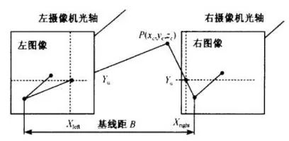
The figure above shows a schematic diagram of simple head-up binocular stereo imaging, the distance between the projection centers of the two cameras, ie the baseline distance B. The two cameras view the same feature point P of the space-time object at the same time, and acquire the images of the point P on the “left eye†and the “right eye†respectively. Their coordinates are Pleft=(Xleft, Yleft); Pright=(Xright). , Yright). When the images of two cameras are set on the same plane, the Y coordinate of the image coordinates of the feature point P must be the same, that is, Yleft = Yright = Y. The following relationship can be obtained from the triangular geometric relations:
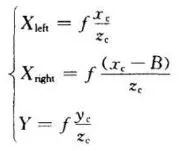
The parallax is: Disparity=Xleft-Xright. From this, the three-dimensional coordinates of the feature point P in the camera coordinate system can be calculated:
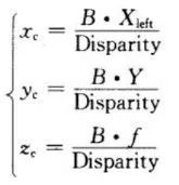
Therefore, any point on the left camera image surface can determine the three-dimensional coordinates of the point as long as it can find the corresponding matching point on the right camera image surface. This method is a point-to-point operation. As long as there are corresponding matching points on all the points on the image plane, the above operations can be performed to obtain the corresponding three-dimensional coordinates.
2.2 Binocular stereo vision mathematical model
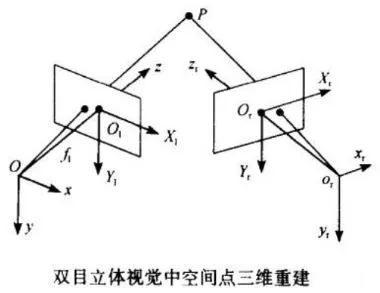
Based on the analysis of the simplest three-dimensional measurement principle of binocular stereo vision, we now have the ability to consider the general situation. As shown in the figure above, let the left camera O-xyz be located at the origin of the world coordinate system and no rotation occurs. The image coordinate system is Ol-X1Y1 and the effective focal length is fl; the right camera coordinate system is Or-xyz, and the image coordinate system is Or- XrYr, effective focal length fr. Then according to the projection model of the camera we can get the following relation:

Since the positional relationship between the O-xyz coordinate system and the Or-xryrzr coordinate system can be expressed by the space transformation matrix MLr:

Similarly, for the spatial point in the O-xyz coordinate system, the correspondence between the two camera surface points can be expressed as:

Thus, the spatial point three-dimensional coordinates can be expressed as
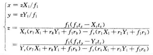
Therefore, as long as we obtain the left and right intra-computer parameters/focal distances fr,fl and the image coordinates of the spatial point in the left and right cameras by the computer calibration technique, the three-dimensional space coordinates of the measured points can be reconstructed.
Nano Core For Electronic Watt-hour Meter
The resistance DC component magnetic core has strong resistance DC component ability, wide current range, few additional circuits and devices, strong reliability and insensitive to interference.
The performance of resisting DC iron core
The resistance DC composite single magnetic core is a single resistance DC magnetic core, which has the characteristics of high linearity, high precision, easy phase error compensation and good high and low temperature characteristics. At the same time, compared with the composite core, the single core has stronger stability and smaller volume.
The application of best magnetic core
Our excellent magnetic iron core has high permeability,low coercivity and loss,excellent performance on DC immue and temperature stability that can be widely used to the electronic watt-hour meter,resistance DC component transformer and electrical power system measurement.
Anyang Kayo Amorphous Technology Co.,Ltd. , https://www.kayoamotech.com