A novel sandwich structure MEMS microwave power sensor structure is proposed. Compared with the conventional sensor, the new structure has a small heat loss due to the vertical heat transfer method. The temperature distribution of the thermopile is simulated with the same power input, and the temperature of the sandwich-structured thermopile is higher than that of the conventional structure, so it has higher sensitivity. At the same time, the impedance matching characteristics of the two structures are simulated, and the difference is not large. In the frequency range of 1 to 6 GHz, the return loss of the sandwich structure is less than -30 dB; in the frequency range of 6 to 20 GHz, the echo is The loss is less than -20 dB, showing good matching characteristics.
The power of the microwave signal is one of the most important parameters in the microwave circuit and the microwave system. The microwave power sensor can be used to measure the power of the microwave signal, and the microwave power sensor based on the thermoelectric conversion is the most accurate one of the various types of sensors. _1]. With the development of the economy and the advancement of technology, this sensor has been widely used to measure the output/input power of the microwave transmitter/receiver, the output power of the oscillator, the output level of the signal source, etc., with fast response and high Sensitivity, wide frequency band and high burnout level have many advantages in defense, communication, scientific research and other fields.
So far, many literatures [2-5] have reported various types of microwave power sensors based on thermopile type. The structure is shown in Figure 1. It is received by a coplanar waveguide (CPW) as a transmission line. Measuring the microwave power, placing two 100 Q matching resistors at the end of the coplanar waveguide to convert the absorbed microwave power into heat, which causes the temperature of the thermopile placed near the resistor to rise, according to the Seebeck effect, in the thermopile two The terminal has a DC voltage output, and by measuring this voltage, the power of the input microwave signal can be obtained. Traditional microwave power sensors have always had low sensitivity problems because the terminal load resistors have a large amount of heat loss during the heat transfer process. In order to reduce the measurement errors caused by various heat losses, some literatures have adopted various complexities. The process forms a sensor structure such as cantilever beam [63, island [7], substrate hollow [8], to improve the thermal resistance of the sensor to reduce the above various heat losses, these measures are improved to some extent. The accuracy of power measurement, but also the difficulty of the process, in order to solve the above difficulties, this paper proposes a new type of sandwich structure MEMS microwave power sensor, which can improve the measurement accuracy of the sensor to a large extent and reduce the complexity of the process. degree.
Terminal load resistance thermopile
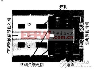
Figure 1 Traditional microwave power sensor structure
1 New microwave power sensor structure and working principleConventional microwave power sensors have various heat losses, including heat transfer, heat convection, and thermal radiation losses. Among them, the heat conduction loss is the most serious, because the terminal load resistance is transferred in the form of heat transfer in the horizontal direction through the gallium arsenide substrate during the heat transfer process, which causes a large amount of heat loss in the middle, so the sensitivity is not affected by this. In order to solve the above difficulties, this paper proposes a new type of microwave power sensor structure, the cross-sectional view of which is shown in Figure 2.
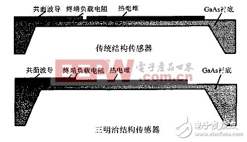
Figure 2: Traditional structure and sandwich structure sensor profile
As can be seen from Figure 2, compared to the conventional structure, the new structure uses four parallel 200 Q terminal load resistors to be divided into upper and lower points.
The vertical structure of the cloth replaces the horizontal structure in which two i00 Q load resistors are used in the conventional structure, and the thermopile is sandwiched between the resistors, referred to herein as a sandwich structure. Compared with the traditional microwave power sensor structure, the sandwich structure adopts the form of vertical heat transfer, which greatly reduces the heat loss and greatly improves the sensitivity.
2 software simulation2.1 Temperature field simulation
The finite element software ANSYS was used to simulate the terminal load resistance and thermopile temperature distribution of the sandwich structure. The ambient temperature was set at 300 K, the height of the GaAs substrate in the sandwich structure sensor was 10 tLm, and the width of the center plane of the coplanar waveguide was i00 tLm. The height is 2tLm, the length is 500 m, the slit width is 58 m, and the thermopile length is 200 p. m, the simulated temperature distribution is shown in Figure 3. It also simulates the temperature distribution of conventional sensors with the same structural dimensions and compares the thermopile heat of sandwich and conventional sensors.
End temperature distribution, as shown in Figure 4.
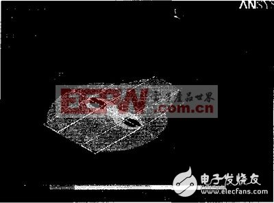
Figure 3 sensor temperature profile
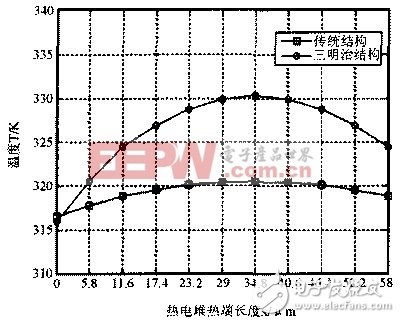
Figure 4 Thermopile temperature profile
As can be seen from Figure 4, in the case of input of the same power (20mw), the hot end of the thermoelectric stack of the sandwich structure (close to the terminal load
The end of the resistor has a higher temperature distribution, and the highest point temperature reaches 331 K, which is higher than the highest point of the conventional structure by about 10 K. Therefore, in the case where the temperatures of the cold ends of the two structures (the end opposite to the hot end) are substantially equal, Sensitivity expression by thermopile:
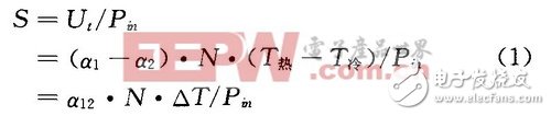
It can be seen that the hot end and the cold end of the sandwich structure have a higher temperature difference, so the new microwave power sensor has a higher ratio than the conventional one in the case where the input power P], the thermocouple logarithm N and the Seebeck coefficient are constant. The sensor has a much higher sensitivity.
2.2 S parameter simulation
The sensor in this paper introduces a coplanar waveguide as a transmission line of the microwave signal to be measured into the measurement system, and its characteristic impedance is 50 Q. In order to convert the microwave signal into heat, four pure resistive load resistors are placed at the end of the CPW, each with a resistance of 200 Q. For microwave signals, the four 200 Qs are connected in parallel, thus forming a 50 Q load equal to the characteristic impedance of the CPW to achieve impedance matching.
The high-frequency simulation software HFSS is used to simulate the return loss of the traditional structure and the sandwich structure. The sensor structure parameters used in the simulation are the same as above, and the simulation results are shown in Fig. 5.
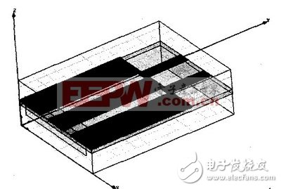
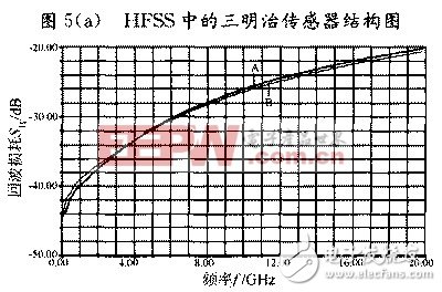
Figure 5(b) S11 simulated using t on H
(A curve is a sandwich structure; B curve is a traditional structure)
It can be seen from Fig. 5(b) that the sandwich structure is basically consistent with the return loss of the conventional structure. In the frequency range of 1 to 6 GHz, the S of the sandwich structure is less than one 30 dB, in the frequency range of 6 to 2O GHz. , S is less than a 20 dB, which maintains a small loss and shows good matching characteristics.
3 sensor preparation process3.1 Basic unit design
The terminal load resistance in the microwave power sensor can be prepared by various materials, such as polysilicon resistor, nickel chrome resistor, tantalum nitride resistor, etc., but since the heat of the resistor is the core of the sensor heat conduction, the temperature of the material used for the resistor is required. The coefficient should be as small as possible, and for the stability of the entire sensor, the absorbing resistor must have the ability to work for a long time. According to the process conditions, and considering the accuracy and stability of the resistor and the temperature coefficient of the material, a tantalum nitride film resistor is used as the terminal load. The basic design requirements for thermopiles are to achieve small time constants, high response rates, and small internal resistance. These parameters of the thermopile are determined by the materials that make up the thermopile and their structure. After the material of the thermopile and the structure of the thermopile are determined, the performance of the thermopile is primarily determined by the size and logarithm of the thermocouple. Reducing the length of the thermocouple can reduce the internal resistance and time constant of the thermopile; increasing the length of the thermocouple can increase the temperature difference between the hot and cold ends; increasing the number of thermocouples can reduce the time constant, increase the response rate, and increase the detection rate. But at the same time increased internal resistance. In the design, the performance parameters of these thermopiles should be fully considered and compromised to obtain the best structure. Considering the actual situation of the process line, here we use doped GaAs and Au as the thermocouple's two arms to form the thermopile. So that not only can have a higher Seebeck coefficient but also a smaller internal resistance, and try to lengthen the arm length to obtain a higher temperature difference while making the structure
The number of thermocouple pairs exceeds 2O to improve the performance of the thermopile, and accordingly it is also beneficial to increase the sensitivity of the sensor.
3.2 Preparation process
Here, a GaAs monolithic microwave integrated circuit (MMIC) Z-Art is used to realize the structure of the sandwich MEMS microwave power sensor, and the MEMS processing process is used to remove the substrate under the hot end of the thermopile by back etching to reduce heat loss. The process flow diagram of the sandwich microwave power sensor is shown in Figure 6 ((a) ~ (g)).
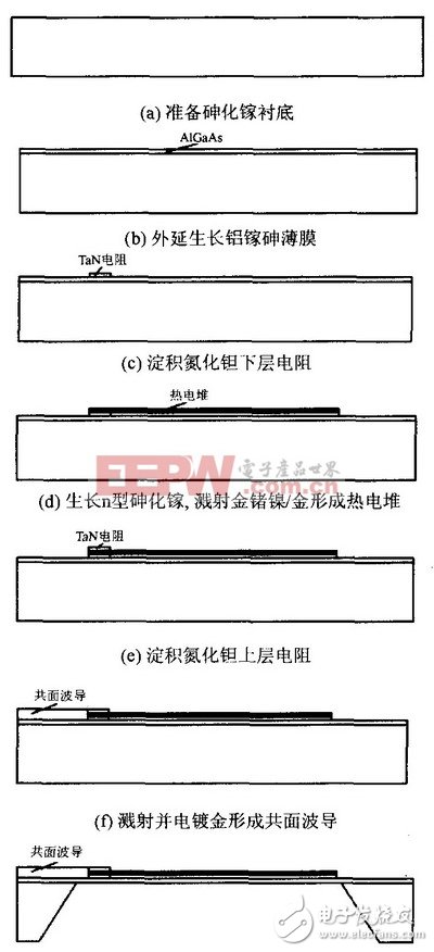

Figure 6 Schematic diagram of the process
4 ConclusionThis paper presents a new type of sandwich structure MEMS microwave power sensor. This new type of sensor is based on the principle of heat transfer. It uses four parallel 200 Q terminal load resistors to distribute the three-dimensional structure up and down to achieve vertical heat transfer, which is different from the traditional microwave power sensor horizontal heat transfer mode. The sensitivity has been greatly improved. The ANSYS was used to simulate the terminal load resistance and thermopile temperature distribution of the sandwich structure and compared with the traditional structure. By comparison, it can be found that the hot end of the sandwich thermopile has more input with the same power (20 mW). The high temperature distribution, the highest point temperature reaches 331 K, which is higher than the highest point of the traditional structure of about 10 K. Therefore, in the case where the cold junction temperatures of the two structures are substantially equal, the hot and cold ends of the sandwich structure have a higher temperature difference because of the sensitivity. It is proportional to the temperature difference between the hot and cold end of the thermopile, so this new microwave power sensor has much higher sensitivity than conventional sensors. At the same time, the return loss of the traditional structure and the sandwich structure is simulated by HFSS. The sandwich structure is basically consistent with the return loss of the conventional structure. In the frequency range of 1 to 6 GHz, the S of the sandwich structure is less than -30 dB, at 6 to 2O. In the frequency range of GHz, S is less than -20 dB, maintaining a small loss. Finally, the manufacturing method and process steps of the new sensor are given.
220V To 110V Transformer,220 To 110 Converter,220 To 110 Voltage Converter,110V Transformer
zhejiang ttn electric co.,ltd , https://www.ttnpower.com