The event is the trigger source of the interrupt, and the corresponding interrupt mask bit is opened, and the event can trigger the corresponding interrupt. Events are also the trigger source for other operations, such as DMA, and the transfer and update of shadow registers in TIM; interrupts cannot trigger these operations, so distinguish events from interrupts. When you only need to generate an interrupt and do not want to trigger other operations, you can use the event mask register.
In STM32, interrupts are not equivalent to events. An interrupt must correspond to an event, but an event does not necessarily correspond to an interrupt.
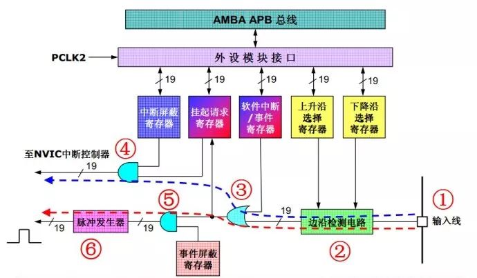
This picture is a schematic diagram of an external interrupt line or an external event line. The signal line is marked with a diagonal line. The note next to the 19 mark indicates that there are 19 sets of such lines. The blue dotted arrow in the figure. The transmission path of the external interrupt signal is indicated. First, the external signal enters from the chip pin of number 1. After the number 2 edge detection circuit, the OR gate of the number 3 enters the interrupt pending request register, and finally the gate of number 4 is passed. Output to the NVIC interrupt detection circuit. This edge detection circuit is controlled by the rising edge or falling edge selection register. The user can use these two registers to control which edge is required to generate an interrupt because the rising edge or falling edge is selected to be 2 parallel. Register control, so the user can select both rising and falling edges, and if there is only one register control, then only one edge can be selected.
Pressing is the OR gate number 3. The other input to this OR gate is the software interrupt/event register. From this it can be seen that the software can request an interrupt or event in preference to the external signal, ie when the software interrupt/event register corresponds. When the bit is "1", the OR gate of number 3 will output a valid signal regardless of the external signal.
After an interrupt or event request signal passes through the OR gate of number 3, it enters the suspend request register. Until then, the interrupt and event signal transmission paths are identical, that is, the external signal is recorded in the suspend request register. Level change.
The external request signal finally passes the AND gate of number 4, and sends an interrupt request to the NVIC interrupt controller. If the corresponding bit of the interrupt mask register is "0", the request signal cannot be transmitted to the other end of the AND gate, and the interrupt is realized. shield.
Understand the request mechanism of the external interrupt, it is easy to understand the request mechanism of the event. The red dotted arrow in the figure indicates the transmission path of the external event signal. After the external request signal passes the OR gate of number 3, it enters the number 5 and The gate, the function of this AND gate is similar to the gate of number 4, used to introduce the control of the event mask register; finally, a transition signal of the pulse generator is converted into a single pulse, which is output to other functional modules in the chip. In this picture, we can also know that from the external excitation signal, the source of the interrupt and the event can be the same. The reason is divided into two parts. Because the interrupt requires the CPU to participate, the software interrupt service function is required. The result of the completion of the interrupt; but the event is generated by the pulse generator, and the result of the event is automatically completed by the hardware. Of course, the corresponding linkage components need to be set first, such as causing DMA operation, AD conversion, etc.;
Simple example: External I/O triggers AD conversion to measure the weight of external items; if a traditional interrupt channel is used, an I/O trigger is required to generate an external interrupt, an external interrupt service routine initiates an AD conversion, and an AD conversion completes the interrupt service routine submission. As a result; if an event channel is used, the I/O trigger generates an event, and then the linkage triggers the AD conversion, and the AD conversion completion interrupt service routine submits the final result; in contrast, the latter does not require the software to participate in the AD trigger, and the response speed is also more block; If you use an event to trigger a DMA operation, you can complete some of the linked tasks without software involvement.
to sum up:
It can be as simple as possible that the event mechanism provides a completely automatic hardware-completed trigger to the resulting channel, without software involvement, reducing CPU load, saving interrupt resources, and improving response speed (hardware is always faster than software). ), is an effective way to use hardware to improve the ability of the CPU chip to handle events.
LAN CABLE Cat5e/Cat6/Cat7/Cat8 Cable
CIXI LANGUANG PHOTOELECTRIC TECHNOLOGY CO..LTD , https://www.cxblueray.com