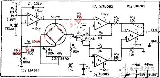
It is common to work in a bridge manner with strain gauges, magnetic resistance elements, semiconductor pressure sensors, and the like. The arrangement has balanced drive and method, and it also includes constant voltage drive and constant current drive. This circuit uses the constant current of the number MA to bias the sensor imbalance and is received by the instrumentation amplifier. The sensor uses a diffusion pressure sensor P-3000S-102G with a pressure range of 0~1KG/CM2.

Â
Circuit working principleThe OP amplifier A1 is a constant current output circuit. The current magnitude is determined by the reference voltage VZ and the sensing resistance. The maximum resistance of the variable resistor is used in this circuit. Otherwise, the output of the OP amplifier will be saturated and the operation will be unstable. The bridge resistance is 4.7K±30%. If there is a bias current of 1.5MA, an equivalent voltage of 9.165V will be generated. A1 must output a voltage of 10.425V, which is the sensing voltage and bridge. The effect voltages are added. The zeroing method is to make the bridge slightly unbalanced and output a certain voltage for zero adjustment. If you use the next level of instrumentation amplifier for zero adjustment. The balanced input amplifier is provided with a buffer filter that filters out high frequency noise, and the time constant is determined based on the highest response frequency.
The instrumentation amplifier is a standard configuration. The gain AV of this circuit is determined by AV=1+(2R3/RG). The sensor output sensitivity is 100±30MV/FS. To get the output voltage of 0~+1V, the AV should be equal to 7.7. ~14.3 times. The calculation method of RO is RO=2RS/(AV-1) according to the above formula, so RO=1.5~3K, considering a little margin, a 2K variable resistor is connected in series on 1K.
AdjustmentIn the case where the sensor is not pressurized, the VR1 is adjusted so that the bias current IB is 1.5MA. Disconnect one end of the sensor and connect the jumper for measuring current to measure the current. There is no need to make an accurate adjustment, you can replace VR1 with a fixed resistor.
Use VR2 to zero, in order to make the range of changes not exceed the requirements. R3 and R4 should use high resistance as much as possible. Finally, the pressure of KG/CM2 is applied to the sensor, and VR3 is adjusted until the output voltage is equal to 1.000V. For the sake of caution, data in the range 0~1KG/CM2 should be collected and the linearity error recorded.
Design PointsA sensor using a semiconductor device must have a temperature coefficient. If it is a P-3000S, a laser is used to fine-tune the thick film resistor to have a small temperature coefficient. However, when performing high-precision measurement, the temperature compensation circuit must be considered. A simple method can be used to connect the thermistor with the RO in series, and then adjust the ambient temperature.
Here, a perfect differential amplifier circuit is used. It is often believed that the circuit should have low drift characteristics. In fact, when the sensor output is 100 MV/FS, an ordinary OP amplifier is sufficient.
Component selectionAlthough the sensor used is not listed in the component table, if it is a P3000S-102G, it should be selected in ±0.02/0.04/0.1% FS according to the drift level.
The reference voltage diode must be a 1.2V product.
SMD Magnetic Buzzers are generally smaller than pin type Magnetic Buzzers, with width as low as 4 mm to 9 mm. They are optimized for small devices such as blood glucose meter, clinical/forehead thermometers, photo flashes for cameras, and portable terminals.
Our products are widely used in home appliances, medical devices, cars, electric bicycles, computers, cordless phones, alarm systems. We are able to make 7 to 9 million pieces monthly based on our professional engineers, advanced audio analyzers, ISO 9001, ISO 140001 and QS 9000 certifications.
Magnetic Buzzer,Smd Magnetic Buzzer,Smd Self Drive Buzzer,Waterproof Smd Magnetic Buzzer
Jiangsu Huawha Electronices Co.,Ltd , https://www.hnbuzzer.com