Realize the use of FPGA to randomly generate E in different directions, display on the display through VGA interface, judge whether the direction of the button pressed by the tester is correct, and calculate and display the function of the final vision test result through several rounds of tests.
Device used
The figure below shows the system framework for the entire vision tester. Select both wired and Bluetooth modes via the switch. The manual mode is input through the buttons on the board; the Bluetooth mode is to transmit the direction and confirmation information selected by the tester via the Bluetooth of the mobile phone. The random number module produces the direction of the "E" for each round of testing. The control module compares with the user input, produces a result, and outputs it to the VGA display. At the same time, the current test status is displayed on the digital tube.
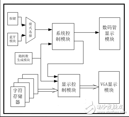
System framework for automatic vision tester
Hardware connection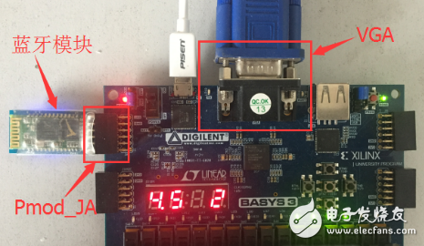
Vision tester hardware connection diagram
Hardware connection as shown :
1) Connect the computer to the microUSB programming port on Basys3 via the USB download cable and set the power selection jumper (JP2, jumper to the left of the Basys3 power switch) to USB power mode. If it needs to be powered by an external power supply, jumper JP2 is set to EXT mode;
2) Connect to the display via VGA;
3) Insert the Bluetooth module into the JA row, make sure that the TX port of the Bluetooth module corresponds to the JA4 port, that is, the port closest to the GND pin.
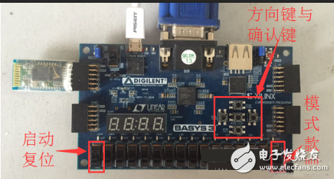
The DIP switch SW0 on the Basys3 board is used to set the wired or Bluetooth mode. When SW0 is set to 0, it indicates the wired mode and input through the buttons on the board. When SW0 is set to 1, it indicates the Bluetooth mode and is input through the buttons of the Bluetooth assistant app.
The five buttons on the Basys3 board indicate the direction selection of up, down, left, and right, and the middle button indicates confirmation selection. The test results are compared only when the confirmation button is pressed.
Since all the button resources on the board are used, the dial switch SW15 is temporarily replaced with the start button and the reset button.
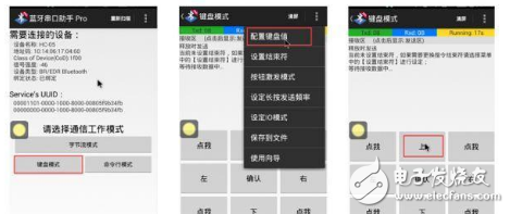
Bluetooth app settings 1
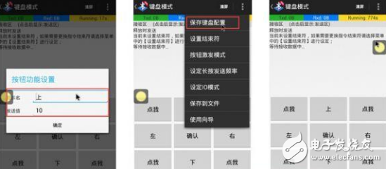
Bluetooth app settings 2
When using the Bluetooth serial port debugging software, after connecting to Bluetooth, select the keyboard mode.
Program download and curingDownload to view the vivado project code
The attachment provides the generated bit files and bin files for direct download or firmware to the FPGA.
1) If you do not need to cure, you can download the bit file directly. Specific steps are as follows:
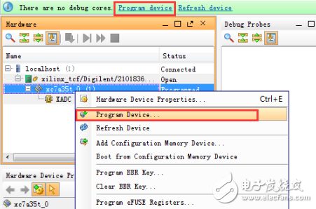
Figure 1: Download Bit File Options
Open the hardware manager and connect to Basys3, select Program device in the green prompt box or right click on the chip model and select Program Device (as shown in Figure 1).
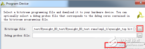
Figure 2: Download the bit file to the FPGA
Select the corresponding bit file and click Program to complete the download (Figure 2).
2) If you need to solidify into the FPGA, you need to follow the steps below.
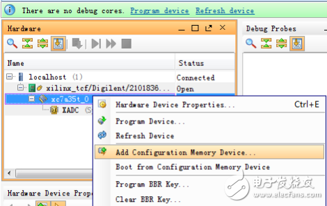
Figure 3: Add Configuration Memory Options
Open the hardware manager and connect to Basys3. Right-click on the chip model in the Hardware window and select Add ConfiguraTIon Memory Device (as shown in Figure 3 above).
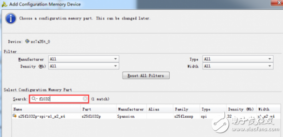
Figure 4: Adding configuration storage
The flash memory model embedded in Basys3 is s25f1032p. After the search is found, click OK to complete the addition (as shown in Figure 4).
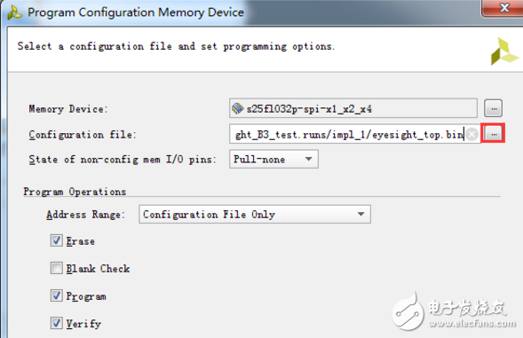
Figure 5: Cure the bin file into configuration memory
The generated BIN file is then written to the flash memory (as shown in Figure 5).
Functional implementation instructions:
1. Randomly generate the symbol "E" for vision test in different directions and display it on the display. The probability of the four directions should be the same.
2. Toggle the SW15 switch on the Basys3 board to start the test. The tester selects the direction of the character seen through the four direction buttons on the Basys3 board, and then presses the middle button to confirm. If the judgment is correct twice or more times, the font size becomes smaller and the next round of testing is performed; otherwise, the test ends, the end of the test is indicated on the screen by VGA, and the visual test result is displayed (completely in accordance with the standard vision comparison table design).
3. During the test, the digital tube displays the level of the test and the number of times each round has been completed to remind the tester to test the progress.
4. After completing a set of tests, the tester can toggle the SW15 switch on the Basys3 board to reset the eyesight test of the other eye.
5, additional features: complete the Bluetooth control mode, improve the test level. Switch between wired and Bluetooth modes via switch SW0. Remote control of the direction button and confirmation button is realized through the Android Bluetooth serial port debugging assistant.
Experimental description:
1. The function of the middle button is defined as the confirmation button;
2, according to the standard vision comparison table 4.0-1M14.51mm, 4.0-5M 72.7mm (visual level - test distance font size), design two modes, wired mode: distance is 1M for vision test, Bluetooth mode for distance vision from 5M test. Due to the limitation of display resolution, the test level range is 3.9-4.0 in wired mode and 3.9-4.9 in Bluetooth mode.
3. The test level starts from 3.9. According to the actual vision test, only one test is performed at level 3.9, and two times at level 4.0. Later, because the symbol "E" is getting smaller and smaller, the tester has three chances and can only answer one mistake. If the first two times are correct, go directly to the next level
High efficient charging speed for Acer laptop, stable current outlet can offer power for the laptop at the same time charge the laptop battery. The best choice for your replacement adapter. The DC connector is 5.5*1.7mm or 3.3*1.0mm. We can meet your specific requirement of the products, like label design. The plug type is US/UK/AU/EU. The material of this product is PC+ABS. All condition of our product is 100% brand new.
Our products built with input/output overvoltage protection, input/output overcurrent protection, over temperature protection, over power protection and short circuit protection. You can send more details of this product, so that we can offer best service to you!
Laptop Adapter For Acer,Charger For Acer,Acer Laptop Adapter ,Ac Adapter For Acer
Shenzhen Waweis Technology Co., Ltd. , https://www.waweispowerasdapter.com