figure 1
one. Phase detector (PD)
There are many circuit forms that make up the phase detector. Only the two phase detectors used in the experiment are introduced here.
Where: Ï„1 = R1 C
Τ2 = R2 C
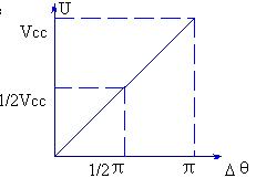
Figure 5
four. Phase model and transfer function of phase-locked loop 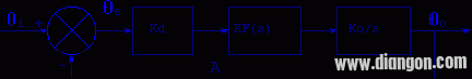
Figure 6
Figure 6 shows the phase model of the phase locked loop. One thing to note is that the phase-locked loop is a phase feedback system in which the phase is flowing, not the voltage. Therefore, studying the phase model of the phase-locked loop gives the complete performance of the loop.
As can be seen from Figure 6:
(1) When the A point is disconnected, the open-loop phase transfer function of the phase-locked loop is
(2) The phase transfer function when the loop is closed is
When the loop filter uses a passive proportional-integral filter, it can be derived by:
, Ï„1 = R1 C , Ï„2 = R2 C

, K = Kd Ko
Ωn is called the natural frequency or natural angular frequency of the system;
x is called the damping coefficient of the system.
It should be noted that ω in the above discussion refers to the angular frequency of the input signal phase, rather than the angular frequency of the input signal itself. If the input signal is a frequency modulated signal, then ω refers to the angular frequency of the modulated signal rather than the angular frequency of the carrier.
Fives. The synchronization of the phase-locked loop and the output frequency of the capture phase-locked loop (or the frequency of the VCO) ω o can track the operating state of the input frequency ωi, which is called the synchronous state. In the synchronous state, there is always ω o = ωi. Under the condition that the phase locked loop remains synchronized, the maximum variation range of the input frequency ωi is called the synchronous bandwidth and is represented by DωH. Beyond this range, the loop loses lock.
When the lock is lost, ω o ≠ωi, if you try to change ωi from two directions, make ωi move closer to ωo, and then make Δωo =(ωi-ωo)↓, when Δωo is small to a certain value, the loop will lose lock. Enter the locked state. This frequency range that causes the PLL to undergo frequency pulling and eventually causes the lock to enter is called the capture band Δωp. The timing of the synchronization band ΔωH, the capture band Δωp and the VCO center frequency ω o is as shown in Fig. 7. 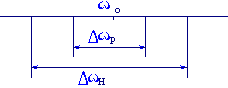
Figure 7
Monocrystalline Solar Panel,Mono Solar Panel,12V Monocrystalline Solar Panel,Monocrystalline 48 Volts Solar Panel
Jiangsu Stark New Energy Co.,Ltd , https://www.stark-newenergy.com