In the electrical schematic, the contactor is often represented as shown below:


These two pictures are the coils and switches of the contactor, respectively.
The principle of the contactor is simply:
When the coil is energized, the contactor switch is closed or opened, functioning to turn the circuit on and off.
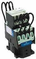
The actual picture is as follows:

The classification of contactors can be classified according to the number of main contacts, the arc extinguishing medium, and the presence or absence of contacts.
The basic parameters of the contactor include: rated voltage, rated current, on-off capability, action value, rated voltage of the attracting coil, operating frequency and service life. Use an example to introduce the meaning of the contactor model parameters:
For example: CJl0Z-40/3
For the AC contactor, design No. 10, heavy duty type, rated current 40A main contact is 3 poles. CJl2T-250/3 is a modified AC contactor with design number 12, rated current 250A, and 3 main contacts.
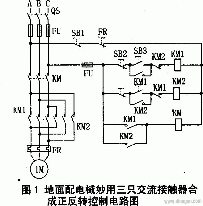
The following describes an example of controlling the start of a motor through a contactor:

The specific working steps of the motor forward rotation start are: 1. Press the switch SB3, 2. Contactor coil  KM1 is energized, 3. Contactor main switch
  KM1 is closed (not shown in the picture), the motor is energized and operates normally. The inverting circuit is not described in detail.
Finally, introduce the English words of the contactor: contactor
Our company offers rubber, and specialty seal and o-ring for molding electronic and electrical Connectors, both circular and rectangular types. We have in house capabilities and quick turn around.
Cable Grommets with various Grommet Shapes, Rib Styles, Slot Shapes, Inner Flanges, and Colors - To have access to our 3D Cable Grommet Design Tool
Silicone Rubber Products,Cable Silicone O-Ring,Rubber Seal,Custom Silicone Seal,Waterproofing O-Ring,Tpe Grommet
ETOP WIREHARNESS LIMITED , https://www.etopwireharness.com