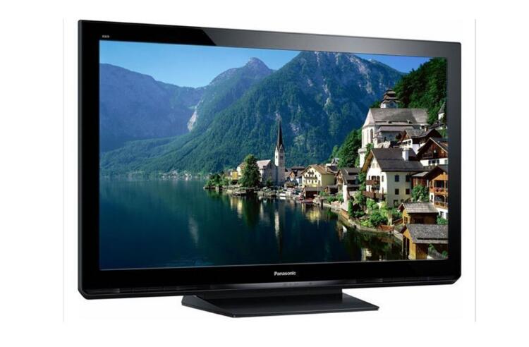
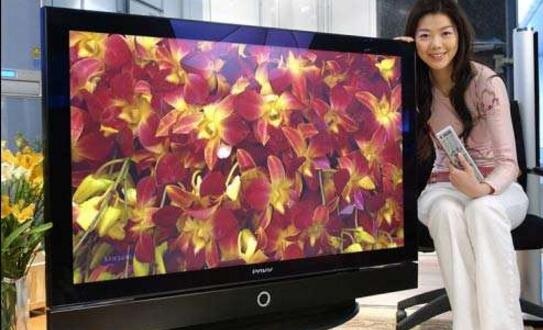
The full name of plasma TV is PlasmaDisplayPanel, which is called plasma TV in Chinese. It is a device that injects mixed gas between two ultra-thin glass plates and applies voltage to illuminate with phosphor. Compared with CRT tube display, it has high resolution, large screen, ultra-thin, rich color and vivid. Compared with LCD, it has high brightness, high contrast, large viewing angle, bright colors and rich interfaces.
Plasma display technology can be divided into two types: DC-type PDP with electrodes in direct contact with gas and AC-type PDP with electrodes covering the dielectric layer. There are three main types of color PDPs researched and developed: single-substrate (also known as surface discharge) AC PDP, dual (also known as counter-discharge) AC PDP and pulse storage DC PDP.

A plasma display panel is a display device that uses a gas discharge, and the screen uses a plasma tube as a light-emitting element. A large number of plasma tubes are arranged together to form the entire full screen. Each plasma tube acts as a pixel, and each pixel consists of three different color illuminators - red, green, and blue. The image of various gray levels and colors is produced by the combination of light and dark and color combinations of these pixels, which is very similar to the principle of CRT. The central component of a plasma tube is the plasma, which is a gas composed of free-flowing ions (charged atoms) and electrons (negatively charged particles). Under normal circumstances, the gas is mainly composed of uncharged particles, that is, a single gas molecule includes the same number of protons (positively charged particles in the nucleus) and electrons, negatively charged electrons and positively charged Protons maintain a perfect balance, so the atom's net charge is zero.
If some electrons are put into the gas by means of increasing the voltage, then it will change immediately. The free electrons collide with the atoms and make the number of electrons inside the atom unbalanced, which will make it positively charged. And produced ions. If a current flows through a stable plasma, the negatively charged particles will rush toward the areas with positively charged particles, while the positively charged particles will also kill those areas with negatively charged particles.
In such a movement, the particles of both sides are constantly striking. These impacts excite the gas atoms in the plasma, causing them to emit light. This works very similar to ordinary fluorescent lamps.
The plasma corresponding to each plasma in the plasma display is filled with helium and neon atoms, and when they are hit, they emit light. Generally speaking, the light emitted by these atoms is only ultraviolet light, and the ultraviolet light is indistinguishable to the human eye. But it is these ultraviolet light that ignites the phosphor and produces the light we can see.

The principle of plasma screen illumination is similar to that of fluorescent lamps. It uses a plasma tube (each plasma tube is a basic pixel) as a light-emitting element, and the screen uses glass as a substrate. The substrate is separated by a certain distance (pitch) and surrounded by a hermetic seal. One discharge space. When a voltage is applied to the electrode, a plasma discharge phenomenon occurs in the krypton mixed gas in the discharge space, and the gas discharge generates ultraviolet rays, and the ultraviolet ray irradiates the phosphor, and the phosphor obtains energy to excite visible light to develop an image.
Power board: Provide power to the screen, other functional modules on the screen, and our own motherboard and video processing board.
X driver board: generates and supplies a driving signal to the X electrode according to the timing signal sent from the logic board.
Y driver board: generates and supplies a driving signal to the Y electrode according to the timing signal sent from the logic board.
Logic board: processes image signals sent from the motherboard, generates addressing drive signals, and provides the required drive signals for the X, Y driver boards and address boards.
Logic BUFFER board (E, F, G): converts the data signals and control signals sent from the logic board into signals required by the COF.
YBUFFER board (upper and lower): The scanning signal on the Y driver board is transmitted to the screen, which is divided into upper and lower parts.
COF: Converts the signal sent from the logic BUFFER board to the address signal used for the screen.
FPC: The scan signal sent from the logic Y-BUFFER board (upper and lower) is connected to the Y-scan electrode on the screen.

Metal Film resistor is Film resistor (Film Resistors) of a kind.It is the high temperature vacuum coating technology will be closely attached to the porcelain nickel chromium alloy or similar bar surface skin membrane, after debugging cutting resistance, in order to achieve the final requirements precision resistance, then add appropriate joint cutting, and on its surface coated with epoxy resin sealing protection.As it is a lead resistance, it is convenient for manual installation and maintenance, and is used in most household appliances, communications, instruments and instruments.
Metal Film Resistors,2W Metal Film Resistors,3W Metal Film Resistor,5W Metal Film Resistor
YANGZHOU POSITIONING TECH CO., LTD. , https://www.cnfudatech.com