Overview:
A pump cabin signal conversion circuit is designed, and the pressure value of the marine pump is sent to the control chip LPC2294 through the pressure sensor. After the data is packaged and packaged, the data is sent to the Ethernet through the Ethernet control chip. In addition, the hardware and software design flow of the conversion circuit is given, and its effectiveness is proved by testing experiments. The design has a good early warning effect on the abnormal state of the marine pump pressure, and realizes the remote monitoring requirements of the crew.
In recent years, China's navigation industry has developed rapidly, and ship safety has increasingly become a concern. According to statistics, since the 1980s, the proportion of shipwrecks caused by deflagration and fire has increased by an average of 1% per year. In China, there are nearly a thousand shipwrecks each year, of which 10% are caused by fires and explosions. Major economic losses and casualties.
As an important part of the ship, the state of various types of marine pumps in the pump cabin directly affects the normal operation of the ship, and the pressure value of the marine pump is the most representative of the various marine pump state parameters. With the universal application of modern sensor technology, it can replace the engineers to correctly realize the inspection management and control of the equipment and systems of the main and auxiliary machines in the nacelle.
This paper proposes a pump cabin signal conversion circuit based on LC2294 processor, which realizes the acquisition and processing of 3 4~20 mA current signals, and converts 4~20 mA current signal into 0~1.6 MPa pressure signal, when the pressure signal After the threshold is exceeded, the pressure over-limit light alarm is performed, the conversion error is ≤0.01 MPa, and the pressure data is uploaded to the host computer through the 10/100 Mbit·s-1 adaptive dual redundant Ethernet. The data transmission frequency is ≥5 times/ s.
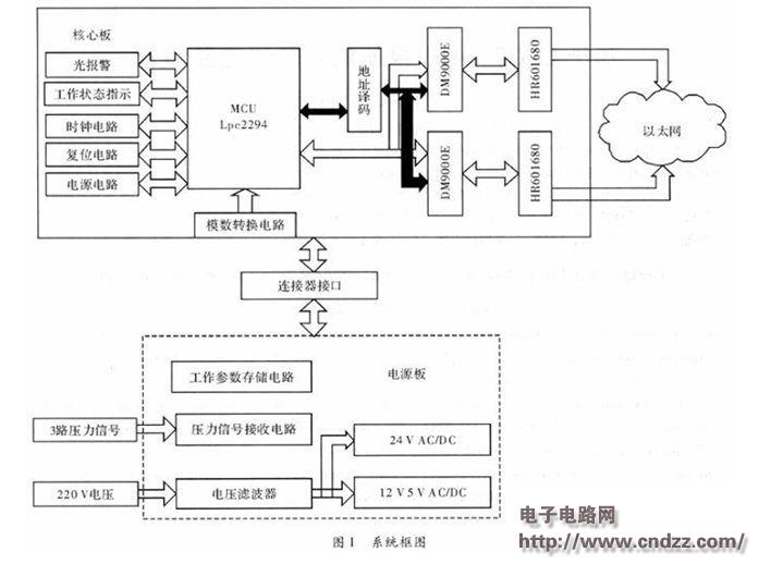
1 Signal Conversion Circuit Design Figure 1 shows the overall scheme block diagram for the design and implementation of the conversion circuit. The LPC2294 acts as the main controller of the signal conversion circuit and extends two 10/100 Mbit·s-1 adaptive network card interfaces to The μC/OS-II real-time operating system serves as the control platform. The TCP/IP protocol stack is tailored and implemented, and data reception and conversion of the pressure sensor and data transmission via Ethernet are completed through software design. 
Figure 2 analog to digital conversion circuit
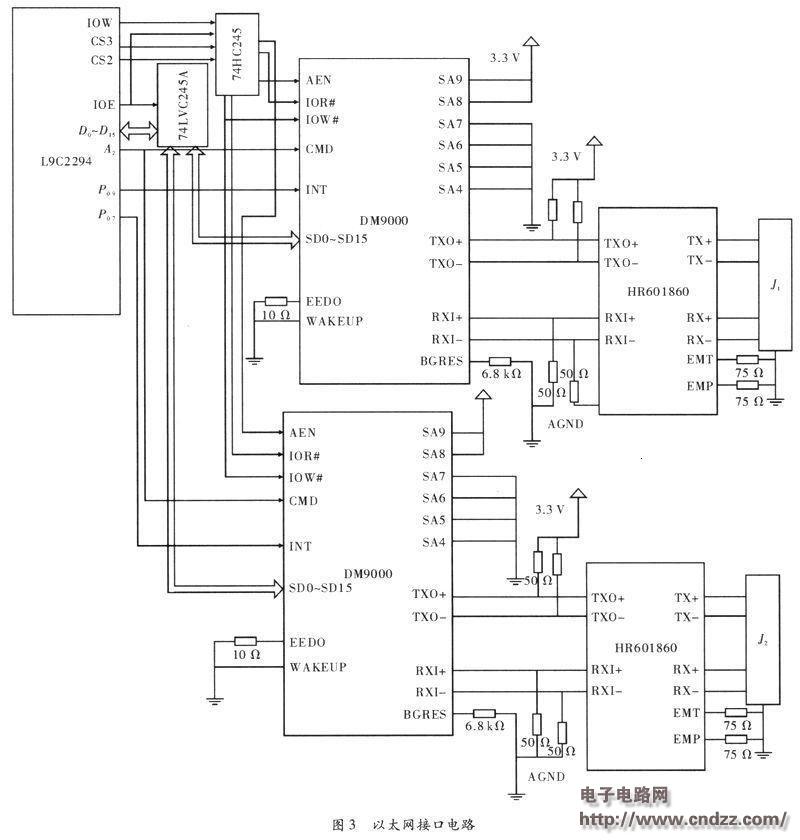
1.4 Ethernet interface circuit design Ethernet interface circuit is mainly composed of DM9000E Ethernet controller and HR601860 network card transformer. The DM9000E is a low-power, high-integration, high-speed Ethernet control chip designed by Davicom. It can be directly connected to the CPU and supports 10/100 Mbit·s-1 Ethernet connection. The interface supports 8 bits and 16 bits. For 32 different processors. The system is designed as two network ports, one primary network port and the other is a redundant network port. In the system, the LPC2294 and DM9000E are controlled by a 16-bit bus and set in 100 MHz full-duplex mode. The two network ports are selected by controlling the CS2 and CS3 pins of the LPC2294 to realize the output chip select signal. In circuit design, CS2, CS3 and 74HC245 pins A2 and A1 are connected, and 74HC245B1 and B2 pins are respectively connected to the redundant network card chip and the ANE pin of the main network card chip. Connect the CMD pins of the two DM9000E chips to the A2 of the LPC2294. The data port address and the index port address of the primary network card chip and the redundant network card chip can be configured as 0x83800000, 0x83800004, and 0x83400000, 0x83400004, respectively. The physical layer transmit and receive ports of the DM9000E, TXO+, TXO-, RXI+, and RXI-, are connected to TPOUT+, TPOUT-, TPIN+, and TPIN- of HR601680, respectively. As shown in Figure 3. 
Previous:24V to 5V circuit diagram
Next: Test board
Related Reading
- • [Solution] Application of safety control SCADA system in urban heating monitoring 2016-08-10 14:18
- • [Solution] The tempering furnace acquisition and transmission system based on Dingshengli R-8188 and R-8018 modules 2016-08-10 14:18
- • [Solution] Yokogawa's latest paperless recorder DX2000 in the remote monitoring system of boiler equipment 2016-08-10 14:18
- • [Solution] Multi-parameter telemetry monitoring system based on ZigBee 2016-08-10 14:18
- • [Solution] Introduction of Schneider's complete solution on continuous vertical packaging machine—Schneider Electric (China) Investment Co., Ltd. 2016-08-10 14:18
- • [Solution] Multi-motor power-down synchronous braking of roving frame based on Delta inverter 2016-08-10 14:18
- • [Solution] Schneider's complete solution in the textile printing and dyeing industry - the main chain sub-drive hot air tenter shaping machine control program 2016-08-10 14:18
- • [Solution] Solution of GE Intelligent Platform Products in Power Plant Production Data Monitoring System 2016-08-10 14:18
Diamond Saw Blade Sharpening Machine
Diamond Saw Blade Sharpening Machine,Grinding Wheel Top Polishing Machine,Diamond Grinding Wheel Sharpening Machine,Diamond Automatic Sharpening Machine
Suzhou Mountain Industrial Control Equipment Co., Ltd , https://www.szmountain.com