Millimeter-wave integrated circuits have the advantages of small size, light weight, and wide bandwidth, and have been widely used in communications, precision guidance, radar, radio astronomy and other technical fields. The U-band refers to a frequency range of 40 to 60 GHz, and the atmosphere has strong absorption characteristics for electromagnetic waves of this frequency band. Therefore, this frequency band is generally used for a multi-path diversity concealment network and system. In the millimeter wave band, the fin line is widely used because it avoids the strict mechanical processing tolerances required for a rectangular waveguide and has the advantages of a planar circuit such as a microstrip line.
This article describes the design and performance of two U-band fin line mixers. The diode used was Alpha's DMK2790 and the circuit was fabricated on a 0.127 mm thick RT-Duroid 5880 substrate. The integrated design of the field analysis software Ansoft HFSS10 and impedance matching principle was used to obtain better mixing characteristics.
2 diode conversion lossConversion loss is the most important technical indicator of the mixer. The conversion loss of a typical mixer consists of three parts:
 (1)
(1)
In the formula, L1 is the mismatching loss, it depends on the match degree of the radio frequency port and the intermediate frequency port of the mixer; L2 is the junction loss caused by the junction capacitance Cj of the diode and the series impedance Rs; L3 is the inherent loss of the ideal diode.
In the case where the local oscillator sufficiently excites the diode, the part of the conversion loss that removes L1 can be approximated as
 (2)
(2)
Where Rb is the reverse resistance of the diode, Zo' is the source impedance seen from the junction of the semiconductor, fc is the cutoff frequency of the diode, and 3.9 dB is the loss due to harmonic suppression by the medium. The final value is approximately 0.5 dB. It can be seen that the cutoff frequency of the diode has a great relationship with the minimum conversion loss of the mixer. The higher the cutoff frequency, the smaller the conversion conversion loss that the mixer may reach, and the better the broadband performance of the mixer. According to the SPICE parameter of the DMK2790 diode in Table 1, the cutoff frequency is
 (3)
(3)
Calculated using Equation (2), the minimum conversion loss of the diode is approximately 5.5 dB at an operating frequency of 45 GHz.
For a given diode, the junction loss L2 is a certain value, and the intrinsic loss L3 depends mainly on the termination condition of the image frequency and the non-linearity of the admittance of the diode. Therefore, the main task of the circuit design is to reduce the mismatch loss L1.
Table 1 SPICE parameters of the DMK2790
Is
AmpRs
WnTD
SCJ0
pFM
0.5E-1241.051E-110.050.26
EG
eVVJ
eV  FCBv
FCBv
VISV
A
1.430.8220.54.01E-05
3 fin line mixer structureThe circuit structure of the first fin-line mixer is shown in FIG. 1 and is a fin line coplanar line structure. In this structure, a 180o mixed junction of fin lines and coplanar lines provides the circuit basis for a single balanced mixer. The two diodes are connected in anti-parallel to the balanced junction. Since the fin-line electric field and the electric field of the suspended coplanar line are orthogonal to each other, the two diodes exhibit in-phase series of the radio frequency signal and the inverse-parallel connection of the local oscillator signal. Provides isolation between RF and LO. The local oscillator power is input by a standard waveguide (WR-19), transitions through a single ridge fin line on the reverse side to a small fin line with a small gap, couples to the front suspension line, and finally transitions to the suspended coplanar line. Applied to the diode pair; the RF signal passes through the waveguide to a gradual transition to the ridge fin line, and the signal is applied to the two diodes, in order to reduce the antireflection of the fin line port.
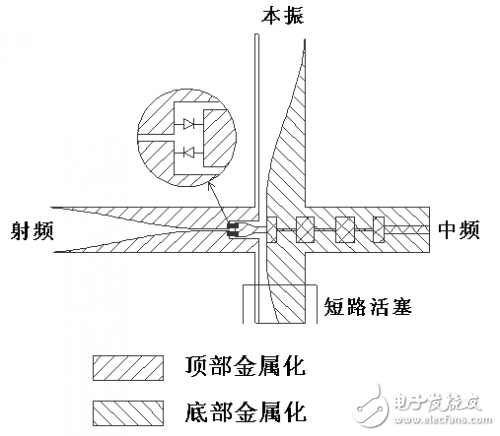
Figure 1 Finline Coplanar Line Structure Mixer
Taking into account the volume, the cosine squared transition was chosen and the transition length was 9 mm. Since the real part of the impedance of the diode is very small, in order to match the impedance of the fin line and the diode, the width of the fin line should be as small as possible. The minimum width of the slit on the RT-Duroid 5880 soft substrate can be 0.1 mm, corresponding to the fins. The line characteristic impedance is approximately 125 ohms; the resulting intermediate frequency signal is output via a seven-section Chebyshev high and low impedance line low-pass filter, which isolates the local oscillator and RF signals through the intermediate frequency signal.
After using three-dimensional field simulation software Ansoft HFSS10 to carry on the independent simulation optimization to each passive part, made the real thing of this mixer, as shown in Fig. 2, the external dimension is 30 & TImes; 30 & Tmes; 30 mm3. Using the output signal of a U-band doubler as the local oscillator of the mixer, the local oscillator frequency is fixed at 46 GHz, the local oscillator power is about 13 dBm, and the radio frequency changes in the range of 40 to 50 GHz. Mixing The conversion loss characteristics of the device are shown in Figure 3.
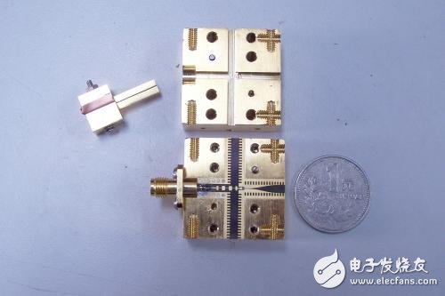
Figure 2 Finline Coplanar Line Structure Mixer
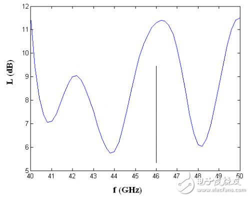
Figure 3 Conversion loss of fin line coplanar line structure mixer
As can be seen from Figure 3, the mixer has a conversion loss of less than 11.5 dB in the 40-50 GHz range, and the conversion loss reaches a minimum of 5.8 dB when the intermediate frequency is about 2 GHz, which is basically close to the theoretical minimum value of the conversion loss. . The local oscillator to RF isolation is greater than 20 dB.
4 fin line mixer structure twoThe circuit structure of the second fin line mixer is shown in FIG. 4 and is a fin line suspension microstrip line structure. A 180o hybrid junction consisting of fin lines and suspended microstrip lines provides the circuit basis for a single balanced mixer. Similarly, two mixer diodes are connected in antiparallel between the fin line and the suspended microstrip line. The electric field of the fin line and the electric field of the suspended microstrip line are orthogonal to each other. The local oscillator power is coupled to the suspended microstrip via a waveguide to a probe that suspends the microstrip and then applied to the two diodes via a suspended microstrip band pass filter that has a local oscillator signal While suppressing the effect of the intermediate frequency signal, the RF signal is also added to the diode after a gradual transition of the waveguide to the ridge fin line; the intermediate frequency signal is derived from the low-pass filter of the high and low impedance line of the suspended microstrip line.
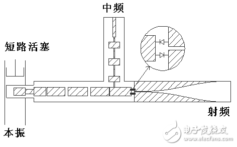
Figure 4 fin line suspension microstrip line structure mixer
The real thing of this mixer is shown in Fig. 5, and its dimensions are 30 & TImes; 30 & TImes; 40 mm3. The local oscillator is fixed at 40 GHz, and the conversion loss characteristic of the mixer is shown in Fig. 6. The mixer has a conversion loss of less than 10.3 dB in the range of 40 to 50 GHz. The local oscillator to RF isolation is greater than 18 dB.
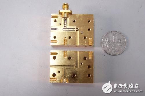
Figure 5 fin line suspension microstrip line structure mixer real
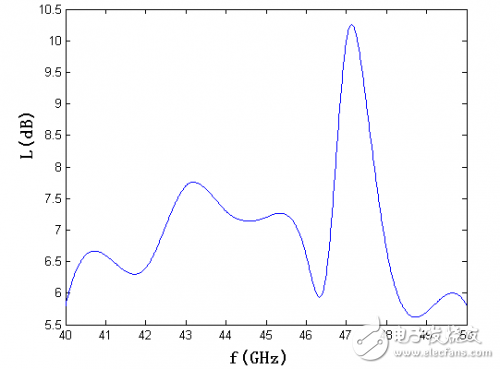
Figure 6 Conversion loss of fin line coplanar line structure mixer
5 ConclusionIn this paper, two U-band fin-line single-balanced mixers are designed and fabricated, and better mixing performance is achieved. When the RF frequency changes in the range of 40 to 50 GHz, the conversion loss of the mixer of the fin line coplanar line structure is less than 11.5 dB, and the conversion loss of the mixer of the fin line suspension microstrip line structure is less than 10.3 dB.
Guangdong Ojun Technology Co., Ltd. , https://www.ojunconnector.com