For a sinusoidal signal, the current flowing through a component and the voltage across it are not necessarily the same. How is this phase difference produced? This knowledge is very important, because not only the feedback signal of the amplifier and the self-excited oscillator should consider the phase, but also the phase difference needs to be fully understood, utilized or avoided when constructing a circuit. Let's explore this issue below. First, we need to understand how some components are constructed. Secondly, we must understand the basic working principle of circuit components. Third, we can find out the reasons for the phase difference. Fourth, we use the phase difference characteristics of components to construct some basics. Circuit. First, the birth of resistors, inductors, and capacitors After long-term observation and experimentation, scientists have figured out some truths, and there have been some unexpected accidental discoveries, such as X-rays discovered by Roentgen and Radiation of Radi discovered by Mrs. Curie. These accidental discoveries have turned into great scientific achievements. The same is true in the field of electronics. When scientists let current flow through the wires, they accidentally discovered the heating and electromagnetic induction of the wires, and invented the resistors and inductors. Scientists also got inspiration from the phenomenon of triboelectricity and invented capacitors. It is also accidental to find a rectifier phenomenon and create a diode. Second, the basic working principle of components - electrical energy → thermal energy inductance - electrical energy → magnetic field energy, & magnetic field energy → electrical energy capacitance - potential energy → electric field energy, & electric field energy → current
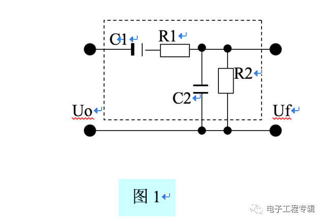
It can be seen that the resistors, inductors, and capacitors are the components of energy conversion. Resistance and inductance realize the conversion between different kinds of energy, and the capacitance realizes the conversion between potential energy and electric field energy. 1 The principle of resistance resistance is: potential energy → current → thermal energy. The positive and negative ends of the power supply store potential energy (positive and negative charge). When the potential is applied across the resistor, the charge flows under the potential difference—the current is formed, and the flow speed is much faster than the out-of-order free motion when there is no potential difference. There is more heat generated by collisions within the resistor or conductor. The positive charge enters the resistor from the end with the high potential, and the negative charge enters the resistor from the lower end of the potential, and the two neutralize inside the resistor. The neutralization causes the positive charge to exhibit a gradient distribution from the high potential end to the low potential end inside the resistor. The amount of negative charge exhibits a gradient distribution from the low potential end to the high potential end inside the resistor, thereby generating a potential difference across the resistor. It is the voltage drop of the resistor. At the same current, the greater the resistance of the resistor to the neutralization, the greater the voltage drop across it. Therefore, R=V/I is used to measure the magnitude of the resistance of the linear resistance (the voltage drop is proportional to the current passing through). The AC signal is expressed as R = v(t) / i(t). Note that there is also the concept of a nonlinear resistor, which has a voltage influence type, a current influence type, and the like. 2 Principle of Inductance and Inductance: Inductance - potential energy → current → magnetic field energy, & magnetic field energy → potential energy (if there is load, → current). When the power supply potential is applied across the inductor coil, the charge flows under the influence of the potential difference - a current is formed, and the current is converted into a magnetic field. This is called a "magnetization" process. If the power supply potential difference between the two ends of the magnetizing coil is cancelled, and the inductor is externally connected with a load, the magnetic field can be converted into electric energy during the attenuation process (if the load is a capacitor, the electric field energy; if the load is a resistor, the current) This is called the "demagnetization" process. The unit that measures how much the inductor is magnetized is the flux linkage - Ψ. The larger the current, the more the inductive coil is punched, that is, the flux linkage is proportional to the current, ie Ψ=L*I. For a given inductor, L is a constant. Therefore, L=Ψ/I is used to express the electromagnetic conversion capability of the inductor, and L is called the inductance. The differential expression of the inductance is: L = d Ψ (t) / di (t). According to the principle of electromagnetic induction, the flux linkage changes to generate an induced voltage. The larger the flux linkage changes, the higher the induced voltage, that is, v(t)=d dΨ(t)/dt. Combining the above two formulas: v(t)=L*di(t)/dt, that is, the induced voltage of the inductor is proportional to the rate of change of the current (derivative to time), and the faster the current changes, the higher the induced voltage. 3 The principle of capacitance and capacitance: potential energy → current → electric field energy, electric field energy → current. When the power supply potential is applied to the two metal plates of the capacitor, the positive and negative charges are respectively concentrated on the two plates of the capacitor under the action of the potential difference to form an electric field, which is called a "charging" process. If the power supply potential difference between the two ends of the charging capacitor is cancelled, and the capacitor is externally connected with a load, the charge at both ends of the capacitor flows outward under the potential difference, which is called a "discharge" process. The charge flows into the current as it accumulates toward the capacitor and flows outward from the two plates of the capacitor. It is important to note that the current on the capacitor is not the charge that actually flows through the dielectric between the two plates of the capacitor, but only the flow of charge from the outside to the two plates of the capacitor during charging, and the charge from the discharge. The flow formed by the two plates of the capacitor flowing outward. In other words, the current of the capacitor is actually an external current, not an internal current, which is different from the resistance and inductance. The unit that measures how much the capacitor is charged is the number of charges - Q. The larger the potential difference between the capacitor plates, the more the capacitor plate is charged, that is, the charge number is proportional to the potential difference (voltage), ie Q=C*V. For a given capacitor, C is a constant. Therefore, C=Q/V is used to express the ability of the capacitor plate to store charge, and C is called capacitance. The differential expression of the capacitance is: C = dQ(t) / dv(t). Since the current is equal to the amount of change in the number of charges per unit time, ie i(t)=dQ(t)/dt, the above two formulas are obtained: i(t)=C*dv(t)/dt, ie the capacitive current and The rate of change of the upper voltage (the derivative of time) is proportional, and the faster the voltage changes, the larger the current. Summary: v(t)=L*di(t)/dt indicates that the current change forms the induced voltage of the inductor (the current does not change and no induced voltage is formed). i(t)=C*dv(t)/dt indicates that the voltage change forms the external current of the capacitor (actually the change in the amount of charge. If the voltage is constant, the external current without capacitor is formed). Third, the component changes the phase of the signal. First of all, the concept of phase is for the sinusoidal signal. The DC signal and the non-periodic signal have no phase concept. 1 The voltage and current on the resistor are in phase because the voltage on the resistor is v(t)=R*i(t). If i(t)=sin(ωt+θ), then v(t)=R* sin(ωt+θ ). Therefore, the voltage on the resistor is in phase with the current. 2 The current on the inductor lags the voltage by 90° because the induced voltage v(t)=L*di(t)/dt on the inductor. If i(t)=sin(ωt+θ), then v(t)=L* Cos(ωt+θ). Therefore, the current on the inductor lags behind the induced voltage by 90°, or the induced voltage leads the current by 90°. Intuitive understanding: Imagine an inductor and a resistor in series with magnetization. From the magnetization process, the change of the magnetizing current causes the change of the flux linkage, and the change of the flux linkage generates the induced electromotive force and the induced current. According to Lenz's law, the direction of the induced current is opposite to the magnetizing current, delaying the change of the magnetizing current, so that the magnetizing current phase lags behind the induced voltage. 3 The current on the capacitor leads the voltage by 90° because the current on the capacitor is i(t)=C*dv(t)/dt. If v(t)=sin(ωt+θ), then i(t)=L*cos (ωt + θ). Therefore, the current on the capacitor leads the phase by 90°, or the voltage is 90° out of phase. Intuitive understanding: Imagine a capacitor and resistor connected in series. From the charging process, there is always a flow charge (ie, current) accumulation before there is a voltage change on the capacitor, that is, the current always leads the voltage, or the voltage is always behind and the current. The following integral equation can reflect this intuitiveness: v(t)=(1/C)*∫i(t)*dt=(1/C)*∫dQ(t), that is, the accumulation of charge changes forms a voltage Therefore, the dQ(t) phase leads v(t); and the process of charge accumulation is the process of synchronous current change, that is, i(t) and dQ(t) are in phase. Therefore, the i(t) phase leads to v(t). Fourth, the application of phase difference of components - RC Wen's bridge, understanding of LC resonance process, regardless of RC Wen's bridge, LC series resonance, parallel resonance, are the voltage and current phase difference of the capacitor or / and the inductor capacity Caused, just like the beat of mechanical resonance. When two sine waves of the same frequency and phase phase are superimposed, the amplitude of the superimposed wave reaches a maximum value, which is a resonance phenomenon, which is called resonance in the circuit. Two sine waves of the same frequency and opposite phase are superimposed, and the amplitude of the superimposed wave is reduced to a minimum or even zero. This is the principle of reducing or absorbing vibration, such as noise reduction equipment. When there are multiple frequency signals mixed in one system, if two co-frequency signals generate resonance, the energy of other vibration frequencies in this system is absorbed by the two co-frequency and in-phase signals, thus playing a role Filtration of other frequencies. This is the principle of resonant filtering in circuits. Resonance needs to satisfy both the same frequency and the same phase. How the circuit selects the frequency by the amplitude-frequency characteristic has been previously described in the RC Wen's Bridge. The idea of ​​LC series-parallel is the same as RC, and will not be repeated here. Let's take a look at the rough estimate of phase compensation in circuit resonance (more accurate phase offset is calculated) 1 Resonance of RC Wen's bridge (Figure 1) Without C2, the current of sinusoidal signal Uo is from C1 → R1 → R2 The Uf output voltage is formed by the voltage drop across R2. Since the branch current is shifted by the capacitor C1 by 90°, the current of the leading phase flows through R2 (the resistor does not produce a phase shift!), so that the output voltage Uf is advanced by 90° Uo. C2 is connected in parallel with R2, and C2 takes the voltage from R2. Due to the hysteresis of the capacitor on the voltage, the voltage on R2 is also forced to lag. (But not necessarily 90°, because there is also the influence of C1→R1→C2 current on the voltage on C2, ie Uf, but at the RC characteristic frequency, the Uf output phase is the same as Uo after parallel C2.) Summary: Shunt capacitor makes the voltage Signal phase lag is called parallel compensation of voltage phase.

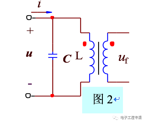
2 LC parallel resonance (Fig. 2) If there is no capacitor C, the sinusoidal signal u is induced to the secondary output Uf through L, and the Uf voltage leads u 90°; in the L primary shunt capacitor C, due to the hysteresis of the capacitor to the voltage, L The upper voltage is also forced to lag 90°. Therefore, the Uf output phase is the same as u after parallel C.

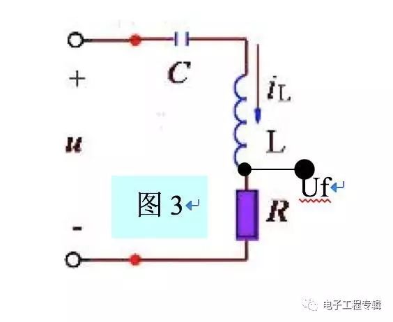
3 LC series resonance (Fig. 3) For input sinusoidal signal u, capacitor C causes the phase of the current on the load R in the series loop to lead u 90°, and the inductance L causes the current phase in the same series loop to lag 90° again. The offset just offsets. Therefore, the output Uf is in phase with the input u.

Summary: (Note that the phase effects are not necessarily 90°, related to other parts, specifically to be calculated)
The series capacitor causes the series branch current to lead in phase, thereby affecting the output voltage phase. The shunt capacitor lags the phase of the parallel branch voltage, affecting the output voltage phase. The series inductance causes the series branch current to phase lag, which affects the output voltage phase. The shunt inductance causes the voltage of the shunt branch to lead, which affects the phase of the output voltage. More concise memory: The capacitor makes the current phase lead, and the inductor makes the voltage phase lead. (both refer to the current or voltage on the component) Capacitance - current lead, inductance - voltage lead.
Solar System Batteries,60Ah Ni-Fe Battery,24V Nickel Iron Battery Bank 60Ah,Ni-Fe Battery 10~80Ah
Henan Xintaihang Power Source Co.,Ltd , https://www.taihangbattery.com