Abstract: This reference design is a complete system design for automotive LED applications. Using the MAX15005 current mode controller, the voltage of a standard lead-acid car battery is raised to 21V, which is used to drive a string of car LEDs.
The following provides a reference design for automotive LED systems. Use the MAX15005 to boost an 8V to 16V automotive battery to 21V to drive a string of 6 to 8 LEDs.
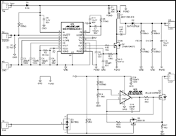
The key parameters of the reference design are listed below, and the required detailed circuit schematic (Figure 1) and bill of materials (Table 1) are given.
Specifications VIN: 8V to 16V (continuous), 40V (transient) VLED + supply voltage: 21V ± 5% at 80mA (maximum) VLED + load range: 10V to 20V at 70mA ILED: 70mA ± 5% brightness adjustment input: 400Hz, 50Ω , Open collector brightness adjustment resolution: 3µs Switching frequency: 385kHz Operating temperature: -40 ° C to + 125 ° C
Detailed drawing (PDF, 92kB)
Figure 1. MAX15005 reference design
Table 1. List of materials
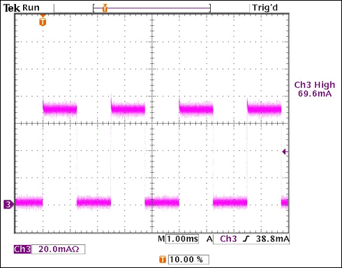
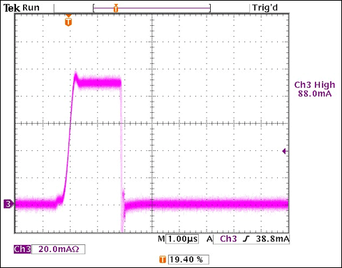
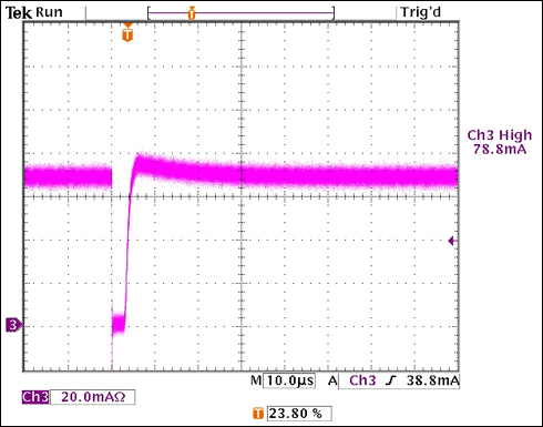
The oscilloscope screenshots in Figures 2, 3, and 4 show the switching waveforms at three different dimming inputs.

Figure 2. ILED waveform measurement with VIN = 14V and 50.0% dimming ratio

Figure 3. ILED waveform measurement with VIN = 14V and 0.1% dimming ratio

Figure 4. ILED waveform measurement with VIN = 14V and 99.9% dimming ratio
The following provides a reference design for automotive LED systems. Use the MAX15005 to boost an 8V to 16V automotive battery to 21V to drive a string of 6 to 8 LEDs.
The key parameters of the reference design are listed below, and the required detailed circuit schematic (Figure 1) and bill of materials (Table 1) are given.
Specifications VIN: 8V to 16V (continuous), 40V (transient) VLED + supply voltage: 21V ± 5% at 80mA (maximum) VLED + load range: 10V to 20V at 70mA ILED: 70mA ± 5% brightness adjustment input: 400Hz, 50Ω , Open collector brightness adjustment resolution: 3µs Switching frequency: 385kHz Operating temperature: -40 ° C to + 125 ° C

Detailed drawing (PDF, 92kB)
Figure 1. MAX15005 reference design
Table 1. List of materials
| Designator | Value | DescripTIon | Part | Footprint | Manufacturer | QuanTIty |
| C1, C5, C6, C8, C10 | 1µF / 50V | Capacitors | GCM31MR71H105KA55L | 1206 | Murata | 5 |
| C2 | 200pF / 100V | Capacitor | GRM2165C2A201JA01D | 0805 | Murata | 1 |
| C3, C13, C14 | 100nF / 100V | Capacitors | GCM21BR72A104KA37L | 0805 | Murata | 3 |
| C4, C7, C9 | 100pF / 50V | Capacitors | GRM2165C1H101JA01D | 0805 | Murata | 3 |
| C11 | 10nF / 50V | Capacitor | GRM216R71H103KA01D | 0805 | Murata | 1 |
| C12 | 10µF / 50V | Capacitor | UUD1H100MCL1GS | SMD | Nichicon | 1 |
| D1 | 1A / 400V | Diode | S1G | SMA | Fairchild | 1 |
| D2 | 200mA / 100V | Schottky diode | BAT41ZFILM | SOD123 | STM | 1 |
| D3 | 200mA / 30V | Schottky diode | STM | SOT23 | STM | 1 |
| L1 | 470µF / 0.86A | Inductor | MSD1260-474 | SMD | Coilcraft | 1 |
| Q1 | 1A / 100V | n-FET | ZXMN10A07Z | SOT89 | Zetex | 1 |
| Q2 | 2A / 55V | n-FET | IRLL014NTRPBF | SOT223 | InternaTIonal RecTIfier | 1 |
| Q3 | 220mA / 50V | n-FET | BSS138 | SOT23 | Fairchild | 1 |
| R1 | 22.1kΩ | Resistor | SMD, 1%, 0.125W | 0805 | Vishay | 1 |
| R2, R4, R6 | 100kΩ | Resistors | SMD, 1%, 0.125W | 0805 | Vishay | 3 |
| R3 | 26.7kΩ | Resistor | SMD, 1%, 0.125W | 0805 | Vishay | 1 |
| R5 | 6.19kΩ | Resistor | SMD, 1%, 0.125W | 0805 | Vishay | 1 |
| R7 | 3.65kΩ | Resistor | SMD, 1%, 0.125W | 0805 | Vishay | 1 |
| R8 | 210kΩ | Resistor | SMD, 1%, 0.125W | 0805 | Vishay | 1 |
| R9, R16 | 2kΩ | Resistors | SMD, 1%, 0.125W | 0805 | Vishay | 2 |
| R10 | 10Ω | Resistor | SMD, 1%, 0.125W | 0805 | Vishay | 1 |
| R11 | 100Ω | Resistor | SMD, 1%, 0.125W | 0805 | Vishay | 1 |
| R12 | 8.66kΩ | Resistor | SMD, 1%, 0.125W | 0805 | Vishay | 1 |
| R13 | 0.51Ω | Resistor | Sense resistor | SL1 | Vishay | 1 |
| R14 | 1.4kΩ | Resistor | SMD, 1%, 0.125W | 0805 | Vishay | 1 |
| R15 | 100Ω | Resistor | SMD, 1%, 0.125W | 0805 | Vishay | 1 |
| R17 | 10Ω | Resistor | SMD, 1%, 0.205W | 1206 | Vishay | 1 |
| IC1 | MAX15005A | Boost controller | MAX15005AAUE + | 16-TSSOP-EP | Maxim | 1 |
| IC2 | MAX4400 | Single op-amp | MAX4400AXK + | 5-SC70 | Maxim | 1 |
The oscilloscope screenshots in Figures 2, 3, and 4 show the switching waveforms at three different dimming inputs.

Figure 2. ILED waveform measurement with VIN = 14V and 50.0% dimming ratio

Figure 3. ILED waveform measurement with VIN = 14V and 0.1% dimming ratio

Figure 4. ILED waveform measurement with VIN = 14V and 99.9% dimming ratio
Insulation PVC Fiberglass Sleeve
Insulation Pvc Fiberglass Sleeve,Pvc Coated Fiberglass Sleeve,Pvc Fiberglass Insulation Sleeve,Pvc Fiberglass Cable Sleeve
Longkou Libo Insulating Material Co.,Ltd. , https://www.sdliboinsulation.com