1 Introduction:
At present, on the global scale, LCD TV is rapidly entering the family with its advantages of advanced technical performance, beautiful and fashionable appearance, stable work and high reliability. It is expected that in the next few years, LCD TV will be the mainstream product in the digital TV era. With the increasing use of LCD TVs, the consumption of electrical energy is also increasing, and the pressure on energy saving and environmental protection has increased dramatically. Therefore, the demand for improving the energy efficiency of LCD TV switching power supplies is becoming more and more urgent. To this end, many government agencies and industry organizations in the world have formulated new power consumption specifications for TVs of different sizes, such as the "Energy Star 3.0" standard in the United States and the "Blue Angel" standard in Germany. Improve the efficiency of the use of electrical energy and reduce electrical energy consumption. The author will discuss how to optimize the design scheme of PFC level, main DC / DC level and standby converter, in order to better improve the energy efficiency of LCD TV switching power supply and meet the new power consumption standard.
2 LCD TV power management system structure:
To improve the energy efficiency of LCD TV switching power supplies, an important aspect is to analyze the structure of the LCD TV power management system, analyze the source of power loss, and take targeted measures to reduce energy consumption.
Usually the LCD TV power management system is composed of three parts: power supply unit, DC / AC inverter and signal processing system. Its typical structure is shown in Figure 1. The power supply unit is composed of PFC pre-regulator, main DC / DC stage and standby converter, which is used to convert AC input voltage (85 ~ 265 V) into lower DC output voltage (24 V, 12 V, 5 V and 3.3 V), where the 24 V or 12 V DC voltage output from the main DC / DC stage is used to power the backlight inverter and signal processing system, and the 5 V or 3.3 V DC voltage output from the standby converter is the standby component and the microcontroller powered by. The DC / AC inverter is responsible for converting 24 V or 12 V DC voltage into a high AC voltage (for example, 1 200 V AC voltage) to power the backlight. The signal processing system is used to control and process sound and image signals.
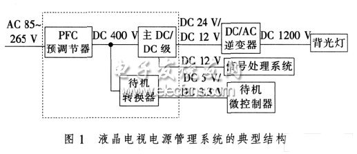
According to the calculation of ON Semiconductor ("On Semiconductor"), the PFC level loss and the main DC / DC level loss of the LCD TV switching power supply are the main losses of the LCD TV switching power supply, of which the PFC level loss accounts for about 40% of the total power loss %, The main DC / DC level loss accounts for about 60% of the total power loss. To this end, the author will optimize the design of the PFC level and the main DC / DC level to reduce the power consumption of the two, and at the same time design the standby converter to meet the new power consumption specification of the standby power consumption of the switching power supply should be less than 1 W standard requirement.
3 PFC pre-regulator solution:
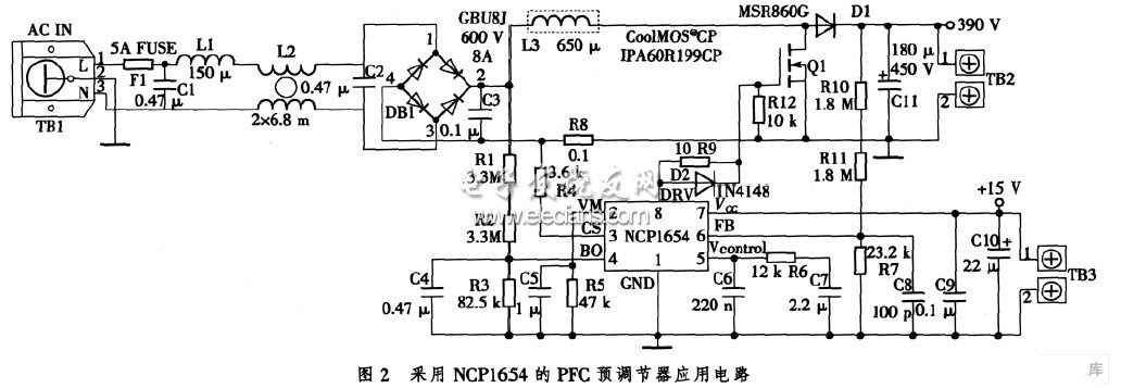
In order to reduce the power consumption of the PFC level and achieve the goal of improving the energy efficiency of the PFC level, the topology and the working mode of the PFC controller need to be considered. Considering the complexity of the design and the total cost of the power solution, the best solution is: the topology is Boost boost structure, and the working mode of the PFC controller is continuous conduction (CCM) mode. For the CCM working mode, the PFC controller can choose the solution provided by ON Semiconductor or Infineon Technology Co., Ltd. (referred to as "Infineon"), which can make the power factor higher than 93% and meet the ICE61000-3-2 standard requirements . However, if you consider the various factors such as cost performance, reliability, and high power factor, choosing the PFC controller NCP165 4 from ON Semiconductor is a more reasonable solution. Using this controller requires very few external components, which makes the design of the PFC class more concise. This controller has very low power consumption and can meet the requirements of improving PFC energy efficiency. At the same time, it also has the characteristics of fast transient response, extremely low startup current and shutdown current, and has many safety protection features, such as inrush current detection, Overvoltage protection, undervoltage detection for open loop detection, soft start, accurate overcurrent limit, true overload limit, etc. In short, it integrates all the features required to build a compact and robust PFC. In addition to the controller part, choosing the new CP series Cool-MOS switch with low on-resistance and low parasitic capacitance and soft recovery boost diode is also the best choice to improve efficiency. In summary, the PFC converter circuit in the LCD TV switching power supply is shown in Figure 2.
Power Meter is a monitoring and testing instrument which determines the power consumption of a connected appliance and the cost of the electricity consumed.
Built-in 3.6V rechargeable Batteries ( . The purpose of the batteries is to store the total electricity and memory setting
Resetting
If an abnormal display appears or the buttons produce no response, the instrument must be reset. To do this,
press the RESET button.
Display Mode
Entire LCD can be displayed for about 1 minute and then it automatically gets into Model. To transfer from
one mode to the other, press the FUNCTION button.
Mode 1: Time/Watt/Cost Display Display duration(how long) this device connect to power source.LCD on first line shows 0:00 with first two figures mean minutes(2 figures will occur while occur at 10 min) and the rest shows seconds. After 60mins, it displays 0:00 again with first two numbers meas hour(2 figures will occur at 10hours)and the rest shows minutes. The rest can be done in the same manner which means after 24 hours, it will re-caculate. LCD on second line displays current power which ranges in 0.0W 〜 9999W. LCD on third line displays the current electricity costs which ranges in O.Ocost 〜 9999cost. It will keep on O.OOcost before setting rate without other figures.
Mode 2: Time/Cumulative electrical quantity Display Display duration(how long) this device connect to power source.
LCD on first line shows 0:00 with first two figures mean minutes(2 figures will occur while occur at 10 min) and the rest shows seconds. After 60mins, it displays 0:00 again with first two numbers meas hour(2 figures will occur at 10hours)and the rest shows minutes. The rest can be done in the same manner which
means after 24 hours, it will re-caculate. LCD on second line displays current cumulative electrical quantity which ranges in 0.000KWH 〜 9999KWH without other figures. LCD on third line displays"DAY"- "1 'Will be showed on numerical part(the other three figures will be showed at carry) which means it has cumulated electrical quantity for 24hours(one day). The rest can be done in the same manner untill the maximal cumulative time of 9999 days.
Mode 3: TimeA^bltage/Frequency Display LCD on first line displays the same as Mode 1 dones. LCD on second line displays current voltage supply (v) which ranges in 0.0V 〜 9999V .LCD on third line displays current frequency (HZ) which ranges in 0.0HZ 〜 9999Hz without other figures.
Mode 4: Time/Current/Power Factor Display LCD on first line displays the same as Mode 1 dones.LCD on second line displays load current which ranges in 0.0000A 〜 9999A. LCD on third line displays current power factor which ranges in 0.00PF 〜 LOOPF without other figures.
Mode 5:Time/Minimum Power Display LCD on first line displays the same as Mode 1 dones. LCD on
second line displays the minimum power which ranges in 0.0W 〜 9999W. LCD on third line displays character of "Lo" without other figures.
Mode 6: Time/Maximal Power Display LCD on first line displays the same as Mode 1 dones. LCD on second line displays the maximal power which ranges in 0.0W 〜 9999W. LCD on third line displays character of "Hi" without other figures.
Mode 7: Time/Price Display LCD on first line displays the same as Mode 1 dones. LCD on third line displays the cost which ranges in O.OOCOST/KWH 〜 99.99COST/KWH without other figures.
Overload Display: When the power socket connects the load over 3680W, LCD on second line displays the''OVERLOAD[ with booming noise to warn the users, (selectable choice)
Supplemental informations:
1: Except [OVERLOAD[ interface, LCD on first line display time in repitition within 24hours.
2: LCD on first line, second line or third line described in this intruction take section according to two black lines on LCD screen. Here it added for clarified purpose.
3. Mode 7 will directly occur while press down button "cost".
4. [UP"&"Down" are in no function under un-setting mode.
Setting Mode
1. Electricity price setting
After keeping COST button pressed lasting more than 3 seconds(LCD on third line display system defaults price, eg O.OOCOST/KWH ),the rendered content begins moving up and down which means that the device
has entered the setting mode. After that, press FUNCTION for swithing , then press "UP"and "DOWN" button again to set value which ranges in OO.OOCOST/KWH 〜 99.99COST/KWH. After setting all above, press COST to return to Mode7 or it will automatically return to Mode7 without any pressing after setting with data storage.
Power meter socket, Energy meter socket, Energy meter cost socket, Power meter cost socket, Energy power meter socket
NINGBO COWELL ELECTRONICS & TECHNOLOGY CO., LTD , https://www.cowellsocket.com