MAX2266 power amplifier with PIN diode switch for CDMA cellular band
Abstract: This article introduces the complete application circuit of the MAX2266 cellular CDMA power amplifier (PA), and provides detailed information of the PIN diode switch, and gives the output power, gain, ACPR, power efficiency (PAE) and idle mode Data such as power supply current. In low power mode (idle current is only 39mA), 15-16% PAE can be provided when the output power is + 15dBm; 11% PAE can be provided when the output power is + 13dBm.
The MAX2266 power amplifier is optimized for CDMA cellular phones based on IS-98 operating in the cellular band. The MAX2266 has optimized efficiency at medium power output. The result is lower average current consumption in typical urban environments and longer talk times.
The MAX2266 standard evaluation board uses a single-pole double-throw (SPDT) switch. This evaluation board has a PAE of 31% at + 28dBm output power and a PAE of 17% at + 16dBm output power. In this application, the PIN diode switch is used instead of the SPDT switch. The use of PIN diodes can achieve better power additional efficiency at maximum output power; in addition, the MAX2266 also has a good PAE at medium and low power output.
Alpha Industries' SMP1321-079 is used in this application. Figure 1 shows the principle diagram of the PIN diode switch. When the MAX2266 is in high power mode, SHDN = high, POW = high, and the PIN diode switches to OFF. At this time, POUT has high impedance. When the MAX2266 is in low power mode, SHDN = high, POW = low, and the PIN diode switches to ON.
L1 and L3 are choke coils, and L2 needs to form a parallel resonance with the capacitance inside the PIN diode. The forward current of the PIN diode is determined by R1. 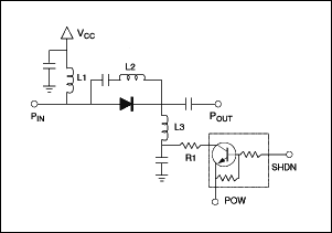
figure 1.
Figure 2 is the output matching section. If the low-power channel and the high-power channel are not connected, the performance of the MAX2266 is almost the same as the performance of the MAX2265. MAX2265 can achieve more than 37% PAE. Poorly isolated low-power channels can cause degradation of PAE and ACPR performance. In high-power mode, the low-power channel requires good isolation to obtain excellent performance in this mode. 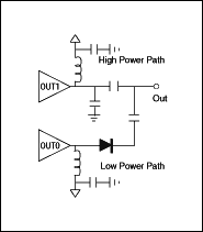
figure 2.
The performance is shown in Table 1. There are three cases of data: maximum output power (+ 28dBm), switching point (+ 15dBm) and medium output power (+ 14dBm). With a PIN diode switch, the PAE at maximum output power is improved because the isolation between the two outputs is increased. At maximum output power, ACPR over -45dBc and 35% PAE can be achieved. Medium output power, can achieve ACPR exceeding -46dBc and 15% PAE when outputting 15dBm; 11% PAE can be achieved when outputting 13dBm. The reactive current is 39mA.
Table 1
(VCC = 3.3V, input signal = CDMA standard signal)
| Frequency (MHz) | Gain (dB) | ACPR (885kHz) (dBc) | ACPR (1.98MHz) (dBc) | PAE (%) | Idle Current (mA) |
| High-Power Mode @ POUT = + 28dBm | |||||
| 824 | 26.72 | -45.53 | -56.03 | 34.45 | |
| 836 | 26.38 | -46.44 | -57.00 | 35.08 | 127 |
| 849 | 25.82 | -45.88 | -56.75 | 35.47 | |
| Low-Power Mode @ POUT = + 15dBm | |||||
| 824 | 27.82 | -45.92 | -61.23 | 15.70 | |
| 836 | 27.62 | -46.75 | -61.34 | 15.97 | 39 |
| 849 | 27.26 | -47.86 | -61.26 | 15.70 | |
| Low-Power Mode @ POUT = 13dBm | |||||
| 824 | 28.06 | -54.16 | -64.10 | 11.19 | |
| 836 | 27.80 | -54.91 | -64.99 | 11.19 | 39 |
| 849 | 27.42 | -54.65 | -62.84 | 11.19 | |
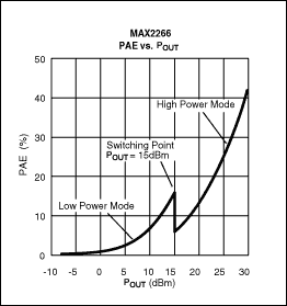
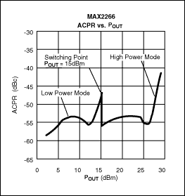
Assuming that the switching point from high-power mode to low-power mode is +15 dBm, Figures 3 and 4 are the results of actual work. In the CDMA system, PAE at medium output power is very important for the actual long-term conversation. If the MAX2266 is switched at + 15dBm, the PAE of medium output power will increase, and at the same time, the ACPR at this point is also less than -46dBc.
 |  |
| image 3. | Figure 4. |

Figure 5. Test setup
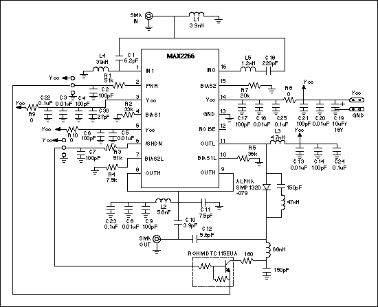
Figure 6. Schematic diagram
4G Ufi and 5G Ufi are two Wireless Router devices in mobile communication technology. All of them can provide wireless Internet connectivity, but the main difference is the network technology and speed they support.
4G Ufi is a wireless router device that uses fourth-generation mobile communication technology (4G). It can connect to the Internet over a 4G network and provide network connectivity to other devices via Wi-Fi or wired connections. Key benefits of 4G Ufi include:
1. High-speed network connection: 4G Ufi can provide faster network speed than the traditional 3G network, which can meet the needs of users for high-speed Internet. This is important for applications with high bandwidth requirements such as online video, games, and downloading large files.
2. Stable connection: 4G Ufi uses 4G network connection, which provides a more stable and reliable connection compared to 3G network. This means users can better enjoy a seamless web experience, whether at home or on the move.
3. Mobility: Since 4G Ufi uses a wireless connection, users can use it anytime, anywhere. This is very convenient for people who need to use the network in different locations, such as travelers, business people, and students.
5G Ufi is a wireless router device that uses fifth-generation mobile communication technology (5G). It can connect to the Internet via 5G networks and offer faster speeds and lower latency. Key benefits of 5G Ufi include:
1. Extremely high Internet speed: 5G Ufi can provide higher Internet speed than 4G networks. According to the specifications of 5G technology, its theoretical peak speed can reach hundreds of megabits per second or even higher. This allows users to download and upload files faster, watch HD videos smoothly, and enjoy a faster Internet experience.
2. Low latency: 5G Ufi can provide lower latency than 4G networks. Latency refers to the time interval between sending and receiving data and is important for real-time applications such as online games, video calls and iot devices. Low latency provides faster response times and a better user experience.
3. Large capacity: 5G Ufi can support more device connections. Due to the high speed and low latency of 5G networks, it can connect more devices at the same time without degrading network performance. This is useful for scenarios where multiple devices need to be connected, such as homes, offices, and public places.
In summary, 4G Ufi and 5G Ufi are both wireless router devices, and the main difference between them is the supported mobile communication technology and speed. 4G Ufi provides high-speed, stable and mobile network connections, while 5G Ufi provides higher network speeds, low latency and large-capacity connections. Which device you choose depends on the user's specific requirements for network performance and requirements.
4G UFI,4G UFI oem,best 4G UFI,cheapest 4G UFI
Shenzhen MovingComm Technology Co., Ltd. , https://www.mcrouters.com