For unlicensed transmitters for remote key (RKE), home automation, home security systems, and other wireless control devices, both the US FCC and the European ETSI specify limits on their transmit power levels. These power limitations require both intentional and unintentional or spurious emissions for these devices. These power limit values ​​are combined and the corresponding test procedures are followed to determine if the device's power radiation meets the established specifications. The relationship between test instrument settings and transmitter radiation characteristics has a significant impact on test results (ie, pass or fail).
This application note describes the modulation spectrum of the amplitude shift keying (ASK) signal, the phase noise of the transmitter, and the effect of the transmitter VCO transient frequency pull on the test results.
ASK modulation spectrumThe ASK modulation spectrum can be understood by modulating an RF carrier signal with a periodic square wave signal and then "correcting" the line to account for the randomness of the data stream.
First, a square wave signal with a period of 2T is regarded as a 1010 with a data rate of 1/T. Non-return to zero (NRZ) data sequence, as shown in Figure 1. The power spectrum of the square wave is shown in Figure 2, where zero frequency represents the carrier frequency, f0. At this time, f0 is composed of a normalized carrier line and a line at (1/2T) odd multiple. The ratio of the power of each line to the power of the carrier (zero frequency) line is given by:
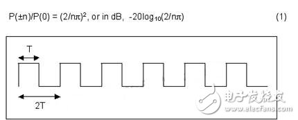
Figure 1. Square wave with a period of 2T
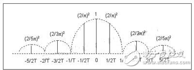
Figure 2. Power spectrum of a square wave with a period of 2T
When the ASK modulated signal is real data, the randomness of the data causes the spectral line of the power spectrum to be corrected to a half cycle sine wave. The mathematical expression for the power spectral density normalized to the carrier frequency is:
![]()
The ratio of the spectral density peak of each side lobes to the spectral density of the carrier frequency is still obtained by Equation 1.
Figure 3 shows the spectrum of the MAX1472 ASK transmitter with a 4kHz square wave (equivalent to 8kbps data rate) modulation. It can be seen that each sidelobe peak is at an odd multiple of 4 kHz (i.e., half of the data rate).
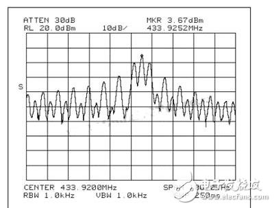
Figure 3. Signal spectrum of a MAX1472 ASK transmitter with 4kHz square wave modulation
Note the relationship between the ASK modulated signal carrier line (or lobe) power and the unmodulated (CW) carrier power. This is important because the FCC and ETSI specifications are sometimes applied to relative power and sometimes to absolute power. If the transmitter steadily radiates (unmodulated) P0 watts of power and then modulates it with an ASK data stream with a 50% duty cycle, the total power of the modulated radiation is halved, which is P0/2. Moreover, the modulation forms a sideband, so the main lobe (carrier) of the spectrum contains only half the power of the ASK modulated signal. Therefore, when the modulated sidelobe power is compared to the CW power of the transmitter, the power ratio in Equation 1 should be further subtracted by 6 dB (i.e., the ratio of CW power to ASK modulated carrier spectral power).
For example, a 315 MHz transmitter that radiates 10 mW of unmodulated carrier power will only radiate 5 mW of power after ASK modulation. Of these 5 mW, only 2.5 mW is present in the carrier lobe, and the remaining 2.5 mW is dispersed in each side lobe. Therefore, when the data rate is 8 kbps (see Equation 1), the power of the 101st side lobes (from the carrier frequency of 404 kHz) is:
![]()
It can be seen that the sidelobe power is not only 44 dB smaller than the carrier lobe power of the ASK modulated signal, but also 50 dB less than the unmodulated CW carrier power.
FCC requirements for ASK transmittersEmission bandwidth
Section 15.231(c) of the FCC states that the intentionally transmitted transmission bandwidth shall not exceed 0.25% of the center frequency, where the transmission bandwidth is determined by the frequency of the radiation spectrum that is 20 dB below the modulated carrier power. The 315MHz and 433.92MHz are the two most commonly used frequencies in the 260MHz to 470MHz unlicensed band. Correspondingly, the maximum allowable bandwidth is 787.5kHz (±394kHz) and 1.085MHz (±542kHz).
From the above formula for calculating the ASK spectral power, it can be easily predicted that the 20 dB bandwidth of the ASK modulated signal can be easily predicted as long as the power is determined to be at least 20 dB lower than the lobe power at the carrier frequency. According to Equation 1, the seventh sidelobe power is 20.8 dB less than the lobe power at the carrier frequency. Therefore, the 20dB bandwidth should be ±7 times the half of the data rate. For a data rate of 10 kbps, the 20 dB transmit bandwidth should be 70 kHz. At a frequency point of 500 kHz from the carrier frequency (a side close to the 0.25% bandwidth limit), the power spectrum of 10 kbps should be 44 dB less than the lobe power at the carrier frequency.
In fact, the measured 20dB bandwidth and the spectral power at 500kHz from the carrier frequency are both larger than the calculated value for three reasons:
The FCC requires that the resolution bandwidth of the measuring device be wider than the modulation side lobes;
The phase noise of the synthesized oscillator increases the power of the side lobes;
The slight pull of the ASK modulation on the VCO causes transient frequency components to appear in the test results.
The measurement bandwidth of the FCC, ie the bandwidth setting of the measuring instrument, is not easy to determine and there are exceptions. Section 15.231(b)(2) of the FCC refers to Section 15.205 of the FCC, while Section 15.205 of the FCC refers to Section 15.35 of the FCC, and Section 15.35 of the FCC finally refers to the 16th edition of CISPR. CISPR-16 states that for transmission applications below 1 GHz, if a quasi-peak detector is used, the measurement bandwidth is set to 120 kHz; if a spectrum analyzer with peak detection is used, the measurement bandwidth is 100 kHz. For a data rate of a few kbps, using this measurement bandwidth to determine the transmission bandwidth seems to be large.
Fortunately, there is a narrower, more realistic FCC measurement bandwidth specification. It is not documented in any documentation, but the compatibility testing company understands this specification and can be verified on the FCC's website, Office of Engineering and Technology. This little-known specification states that the measurement bandwidth must be at least 1% of the allowable 20 dB transmit bandwidth. So for a 315MHz signal, 1% of the 787.5kHz bandwidth is about 8kHz, then setting the bandwidth of the spectrum analyzer to 10kHz will suffice. For the 433.92MHz signal, 1% of the 1.085MHz bandwidth is slightly larger than 10kHz. The bandwidth of the spectrum analyzer must now be set to 30 kHz as this is the setting closest to 10 kHz above 10 kHz. For any of the 315MHz and 433.92MHz signals, the measurement bandwidth is below 100kHz.
The phase noise spectral density of phase-locked loop (PLL) transmitters produced by different manufacturers can vary greatly. The Maxim series RF CMOS transmitters have a phase noise density between -85dBc/Hz and -90dBc/Hz when measured at a carrier frequency of 500kHz. This means that the phase noise measured in the maximum FCC bandwidth of 100 kHz is more than 35 dB less than the power at 500 kHz from the carrier frequency. If the data rate is low, the presence of phase noise increases the measured value of the modulation spectrum when measuring the spectrum at a distance of 500 kHz from the carrier frequency, although its theoretical sidelobe power level is more than 35 dB less than the carrier lobe power.
If a wider measurement bandwidth (such as 100 kHz) is used, the measured spectral height is increased by 5 dB due to the transient pull of the ASK modulation on the VCO. A wide-resolution filter with the "Max Hold" function detects these transient spectral changes that only exist for a few microseconds. When the resolution bandwidth of the filter is reduced to 30 kHz or lower, the effect of this phenomenon on the measured spectrum can be substantially eliminated.
With the peak detector or "Max Hold" setting required by the FCC, the measured power can be increased by up to 10 dB in view of the above three factors. Therefore, the transmit bandwidth measurement spectrum at a frequency of 500 kHz from the carrier frequency may be only 20 dB to 25 dB less than the carrier power, although in theory the modulation spectrum is 35 dB to 55 dB smaller. Due to this large difference between the theoretical spectrum and the measured spectrum, high data rate ASK transmitters may have problems during FCC testing. Since the FCC requires consideration of all influencing factors, the spectrum at a distance of approximately 500 kHz from the carrier frequency is 20 dB less than the carrier lobe power. Corresponding to different data rates, Table 1 lists the theoretical spectral heights of the ASK modulated sidebands at a carrier frequency of 500 kHz. The power measured with 100 kHz, 30 kHz and 10 kHz bandwidth is also given.
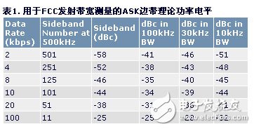
Figure 4 and Figure 5 show the measured spectrum of the MAX1472 ASK transmitter IC using the 100kHz and 30kHz measurement bandwidths, respectively, using a square wave signal with a data rate of 19.2kbps. The difference between the calculated power level and the measured power level is caused by phase noise, VCO transient pull, and "peak hold" measurement techniques. Using a resolution bandwidth of 30 kHz can reduce the power measurement from -25 dBc to -30 dBc, thereby increasing the margin for meeting the emission bandwidth requirements.
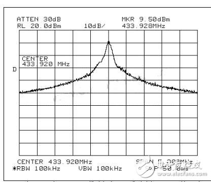
Figure 4. When the spectrum analyzer uses the 100kHz resolution bandwidth for FCC emission bandwidth measurement, the measured MAX1472 modulated signal spectrum, the modulated signal is a 9.6kHz square wave signal.
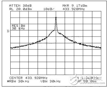
Figure 5. When the spectrum analyzer uses the 30kHz resolution bandwidth for FCC emission bandwidth measurement, the measured MAX1472 modulated signal spectrum, the modulated signal is a 9.6kHz square wave signal.
Spurious radiationSection 15.231(b)(3) of the FCC states that the signal strength of stray radiation must remain below the specified level listed in the table in this section. The table specifies the intentional emission limit value at the carrier frequency and the spurious emission limit value outside the emission bandwidth. These spurious signal strengths are 20 dB lower than the maximum allowable transmission level allowed. That is, if the transmitter is radiating the maximum allowable level, the radiated power outside the transmit bandwidth must be more than 20 dB below the carrier power level. This is in line with the 20 dB emission bandwidth requirement for maximum radiated power. According to CISPR-16, spurious emissions are measured using a quasi-peak detector or a spectrum analyzer with a peak detector. Except that the bandwidth of the spectrum analyzer is set to 100 kHz, the process is much like the measurement process of the emission bandwidth.
It should be noted that if the transmitter does not radiate the maximum allowable power, then the maximum spurious emission level still uses the absolute signal strength values ​​specified in the table. In this case, spurious emissions outside the emission bandwidth may not need to be 20 dB lower than the intentional radiated power.
ETSI requirements for ASK transmitters
In Europe, signals up to +10 dBm are allowed to be transmitted in the frequency band 433.05 MHz to 434.79 MHz. The primary purpose of meeting the requirements of the ETSI EN 300 220-1 specification is to keep the out-of-band emissions below 250nW (or -36dBm) and to remain below 4nW (or -54dBm) in the 470MHz to 862MHz band. The "out-of-band" of the 433 MHz band refers to any frequency other than the 1.374 MHz spectrum of 433.05 MHz to 434.79 MHz. Select 433.92MHz because it is just at the center of the band. With reference to the carrier frequency, any transmission outside of ±870 kHz is “out of bandâ€. There are two emission categories that meet the -36dBm limit requirement. The first type is the signal modulation sideband that falls outside of ±870 kHz. The second category is stray radiation.
Modulation sidebandTable 2 can be constructed using Equations 1 through 3 above. Table 2 is similar to Table 1, except that the distance from the carrier frequency is changed to 870 kHz instead of the approximate 500 kHz required by the FCC.
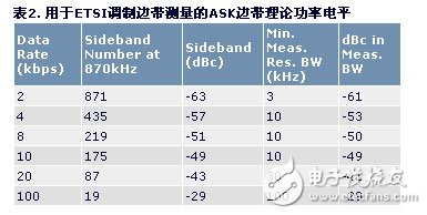
As shown in Figure 3, for each 8 kbps data rate, each sideband is centered at an odd multiple of 4 kHz. That is to say, the 219th harmonic sideband of 4kHz is the first complete sideband except the carrier frequency of 870kHz, and the total power of the sideband must be lower than -36dBm. According to Table 2, the power of the 219th sideband is 51dB lower than the height of the carrier lobe, which seems to well meet the requirement of less than -36dBm. Since the +10 dBm limit corresponds to the measured transmit power of the unmodulated carrier (ETSI EN 300 220-1, Section 8.2), the sideband power is actually 57 dB lower than the unmodulated carrier power and looks better. With the transmitter radiating +10 dBm maximum allowable power, the calculated sideband power is -47 dBm, which is 11 dB lower than the -36 dBm limit requirement. As is the case with the FCC, the transmitter's phase noise and power measurement techniques increase the measured power level above the theoretical value.
This modulation and its measurement process are described in Section 8.6 of ETSI EN 300 220-1. The measurement procedure states that the bandwidth of the receiver (or spectrum analyzer) needs to be large enough to receive all major modulation sidebands and that the peak power is required (the spectrum analyzer is set to "Max Hold"). Standard spectrum analyzer bandwidth settings include 1 kHz, 3 kHz, and 10 kHz, etc. Figures 2 and 3 show that at least 10 kHz bandwidth is required to cover the carrier lobe and the two main sidebands. The 10 kHz bandwidth consists of a sideband (8 kHz zero-to-zero spacing) and a small fraction of adjacent sidebands, which results in a measured power of -46 dBm, which is 1 dB greater than the actual power of a sideband. The peak power measurement may be 10 dB higher than the average power, which will increase the measured power to -36 dBm, just to meet the ETSI requirements. For 8 kbps data rates, some measurement labs may insist on using a 30 kHz resolution bandwidth to receive all major modulation sidebands, which will increase the measurement to -31 dBm. This clearly exceeds the limitations of ETSI, so the data rate needs to be reduced to keep all major modulation sidebands within 10 kHz bandwidth. To ensure that all three lobes are within 10 kHz, the reliable data rate is 5 kbps. Waveform shaping of the modulated pulses can also be performed to achieve higher data rates. Modulation pulse shaping can greatly reduce the power of higher-order modulation sidebands, so even with higher measurement bandwidths, the power at the edge of the band is much lower.
The lower the data rate, the easier it is to meet the ETSI limits. Figure 6 shows the measurement trace of the spectrum analyzer when the ASK modulation of the 433.92MHz, +10dBm carrier is performed with a 1.5kHz square wave. The result is measured by the spectrum analyzer at 434.79MHz (zero scan) with a 3kHz bandwidth. . This is equivalent to a data rate of 3 kbps. The peak amplitude of this trace is approximately -45 dBm, which is -55 dBc relative to the +10 dBm carrier. This result is consistent with the power calculation of the 581th modulation sideband at a carrier frequency of 870 kHz: -65 dBc (or -55 dBm) with respect to +10 dBm, which is increased by 10 dB based on the use of a peak detector. Even with a 10 kHz bandwidth, this modulation meets the ETSI limits.
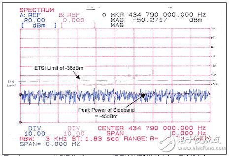
Figure 6. Modulation sideband power of a 3kbps ASK modulated carrier measured at 434.79MHz with a carrier frequency of 433.92MHz.
These calculations and measurement data indicate that pulse shaping is required to radiate the maximum allowable power in the 434 MHz band in Europe at data rates above 5 kbps. In this test, the transient pull of the ASK modulation on the VCO does not increase the measured power because the resolution bandwidth in this measurement is much lower than 100 kHz.
The proposed revision of ETSI 300 220-1 (version 2.1.1, as opposed to the existing 1.3.1 version) will impose more severe restrictions on amplitude and ASK modulated signals. It even requires a resolution bandwidth of 100 kHz in this measurement, regardless of the sideband structure. This version has not yet been adopted. If adopted, it will not take effect within two to three years.
Spurious radiationSection 8.7 of ETSI 300 220-1 defines stray radiation such that carrier and sideband frequency emissions associated with standard modulation tests are not considered and only power radiation in other frequency ranges is considered. This measurement is intended to find unintentional mixing or clock harmonics without regard to the spectral power obtained by modulating the carrier. If possible, the measurement is preferably performed without modulating the carrier, so that the problem of modulating the sidebands is no longer considered. However, it is still necessary to consider the power level of the transmitter phase noise within the measurement bandwidth. The maximum allowable radiation power outside the 433.05 MHz to 434.79 MHz band is -36 dBm, while the 470 MHz to 862 MHz band range is not included, and the radiation limit value for this frequency range is -54 dBm. This power measurement method is different from the modulation sideband measurement method in Section 8.6. The measured power is the average power in the 100 kHz bandwidth. This means that the noise signal (such as phase noise) should not be higher than -86dBm/Hz (-36dBm divided by 100kHz bandwidth) at a power density outside the carrier frequency of 870kHz. If the CW power of the transmitter is +10 dBm, the phase noise density of the transmitter should be lower than -96 dBc/Hz (-86 dBm/Hz divided by +10 dBm unmodulated carrier power).
The phase noise spectral density of the MAX1472 and MAX7044 is approximately -91dBc/Hz, so if the two devices radiate +10dBm of CW power, their spurious emissions are 5dB higher than the limit required by ETSI. If the two devices reduce the radiated power (+5dBm), the ETSI requirements can be met. At a distance of 870 kHz from the carrier frequency, the phase noise spectral density of the MAX1479 is -98 dBc/Hz, so it can radiate a power level of +10 dBm according to ETSI regulations. In the 470MHz to 862MHz frequency range, the power limit of -54dBm is required to be converted to a phase noise density of -114dBc/Hz. All of Maxim's transmitters meet this power level requirement because the low frequency edge (470MHz) of the band is far from the carrier, so the radiated noise comes only from the thermal noise floor of the transmitter.
HDMI Cable
HDMI stands for High Definition Multimedia Interface and is the most frequently used HD signal for transferring both high definition audio and video over a single cable.It is used both in the commercial AV sector and is the most used cable in homes connecting devices such as digital TV, DVD player, BluRay player, Xbox, Playstation and AppleTV with the television.There are many types of HDMI cable:USB to HDMI,Micro HDMI,VGA to HDMI cable,etc..
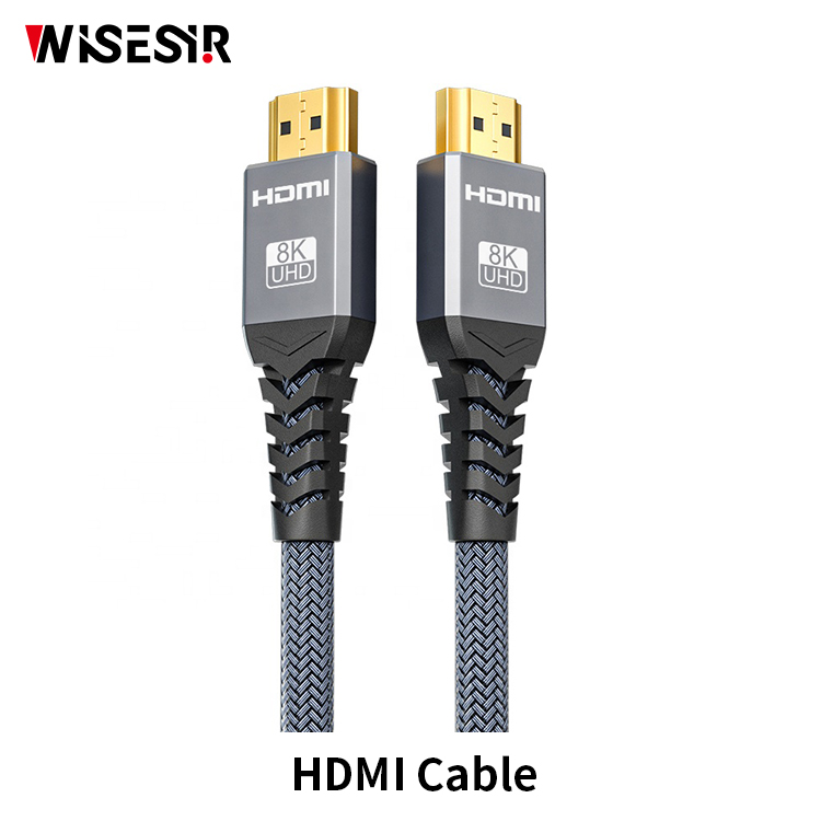
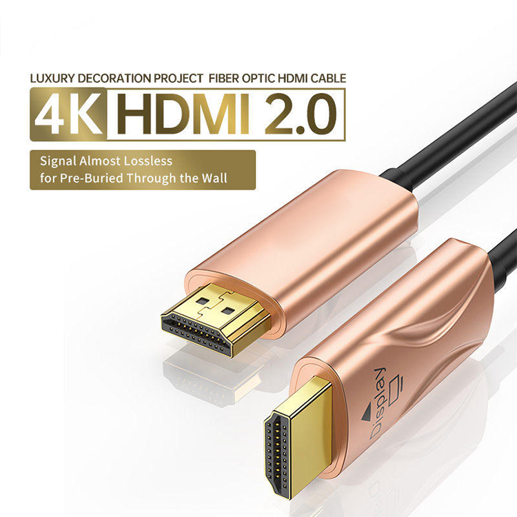
High Speed Hdmi Cable,Hdmi Cable for Tv,Long Hdmi Cable,Hdmi High Speed
Pogo Technology International Ltd , https://www.wisesir.net