In the 21st century, more and more electronic products are appearing in people's daily lives. For example, companies, schools, and TV stations often hold various quizzes, and the rushing scorer is a necessary device.
In real life, it is often the case that two or more coded signals are input at the same time. For example, press two buttons on the computer keyboard at the same time. If the encoder in the computer keyboard is the conventional encoder mentioned above, when the two buttons are pressed at the same time, the encoder in the keyboard will not be able to encode this input state, and an error message will appear. This kind of error message can sometimes have fatal consequences. In order for the encoding company to have a certain output signal output when such an input state occurs, a priority encoder appears.
The priority encoder allows two or more encoded signals to be input simultaneously, and the encoder prioritizes all of the input signals. When multiple input signals occur simultaneously, only the one with the highest priority is encoded.
This time mainly introduced the composition, design and function of the digital display eight-way responder circuit. The circuit is designed with 74 series of common integrated circuits. In addition to the basic answering function, the responder also has timing, timing and alarm functions. The host presets the time for the answer through the time preset switch, and the system will complete the automatic countdown. If someone answers in the specified time, the timing will stop automatically; if no answer is answered within the specified time, the buzzer in the system will sound, prompting the host to invalidate the round, and realize the alarm function. The answer time is invalid.
The responder mainly uses encoders, decoders and latches: it uses 74LS148 to realize the selection of the responder, 74LS279 chip to realize the latching of the number, 74LS192 to realize the decimal subtraction counting, using 555 chip to generate the second The pulse signal is used together to implement the countdown function.
1. Design technology requirements(1) Design an 8-way responder with a number corresponding to the contestants.
(2) It has the function of displaying the sequence number and time of priority, and prohibits the answer of other players.
(3) The host presets the answer time and controls the start and end of the game.
(4) Alarm circuit: When the host presses the “Start†button, it will alarm and enter the rush state;
When the responder sends a rushing signal, the alarm prompts; when the specified rush end time expires, the alarm occurs.
2, the system's composition of the block diagram and working principleBlock diagram of the responder
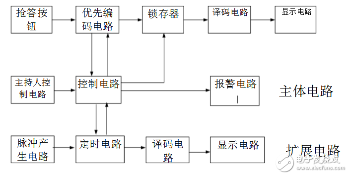
How the system works
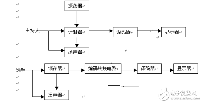
The circuit shown in the figure includes two parts: a main body circuit and an extension circuit. Main body
The road completes the basic answering function, that is, after the host presses the control switch, when the player presses the answer button, the digital tube displays the player number, and at the same time blocks the input circuit, and the other players are ineffective. The extended circuit completes the function of timing answering and alarm function.
The working process of the circuit is: after the power is turned on, the moderator puts the control switch in "clear"
At this time, the responder is in a forbidden state, the player cannot perform the answer, and the time display displays the set time (30s). When the host puts the control switch at the "start", the speaker emits a sound and the responder is in working state. The timer starts counting down. When the player presses the answer button within the time limit, the circuit has to perform the following functions:
(1) The priority encoding circuit determines the number of the responder, and is latched by the latch, and then displays the number of the responder on the digital tube through the decoding display circuit; (2) the speaker emits a short sound;
(3) The control circuit blocks the remaining input codes, prohibiting other players from answering; (4) The control circuit should stop the timer, and the remaining time of the answer is displayed on the digital tube. When the player answers the question, the moderator operates the control. The switch clears the system and returns the system to a forbidden state for the next round of acknowledgment. When the time is up, but no player answers, the system will alarm and block the input circuit, prohibiting the player from answering after timeout.
3, circuit design3.1 Design of the answering circuit
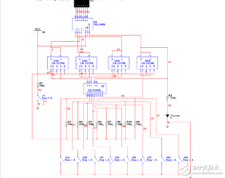
There are two functions of the answering circuit: one is to distinguish the order of the player's buttons, and to latch the number of the priority responder for the decoding display circuit; the other is to invalidate the button operations of other players. The above functions can be accomplished by using the priority code 74LS148 and the RS latch 74LS279. Its circuit composition is shown in Figure 3-1.
The working principle is: when the moderator switch is in the "clear" position, the R terminal of the RS flip-flop is low level, and the output terminals (4Q ~ 1Q) are all low level. Therefore, the BI of the 74LS48 is 0, the display is off; the gate input of the 74LS148 is ST=0, and the 74LS148 is in operation. At this time, the latch circuit does not work. When the moderator switches the switch to the "start" position, the priority encoding circuit and the latch circuit are in the working state at the same time, and the responder is in the waiting state, waiting for the input terminals I7, I6, I5, I4, I3, I2, I1. I0 input signal, when a player presses the key (such as pressing S5), the output of 74LS148 Y2Y1Y0=010, YEX=0
After the RS latch, CTR=1, BI=1, at this time 74LS279 is in working state, 4Q3Q2Q=101, after 74LS48 decoding, the display shows “5â€. In addition, CTR=1, so that the ST terminal of 74LS148 is high level, 74LS148 is in the forbidden working state, and the input of other buttons is blocked. When the pressed button is released, the YLS of the 74LS148 is high, but since the CTR remains at the high level, the 74LS148 is still disabled, and the input signals of other buttons are still not accepted. This ensures the priority of the responder and the accuracy of the answering circuit. When the priority responder answers the question, the moderator operates the control switch S to reset the answer circuit for the next round of answering.
3.2 Timing circuit design
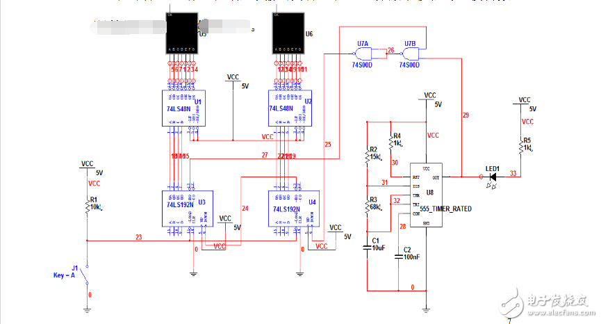
The 7, 6, 2, and 3 pins of the 74LS48 accept the output signal from the 74LS192 and decode it on the digital tube. 74LS192 9, 10, 11, 15 pin completion time setting function, this design requires timing 30 seconds, so the left chip of the 1,15 pin is connected to the high potential, the period is fully connected to the low position, so that the initial time Set to 30 seconds. The 555 chip performs the function of generating a second pulse. The working process is: Before the start of the answer, the set terminal of the 74LS192 is low, in the initial state, the digital tube is displayed as 30, and the 5 pin is connected to the high potential. After the start of the rush, the second pulse rushes to push the chip on the right to start the countdown. At the same time, the signal generated by the right chip is used as the CP signal of the left chip to push the chip on the left side to complete the decimal countdown function. When someone answers the answer, the output of 1Q is 1, after passing the NOT gate, it becomes 0. The second signal is blocked by the AND gate, and the time is stopped to complete the function of displaying the answer time. When it is recorded for 30 seconds, the timing of the left chip is low to the signal output, and the second signal is also blocked, so that the digital tube displays 00. As shown in Figure 3-2
3.3 Alarm circuit design
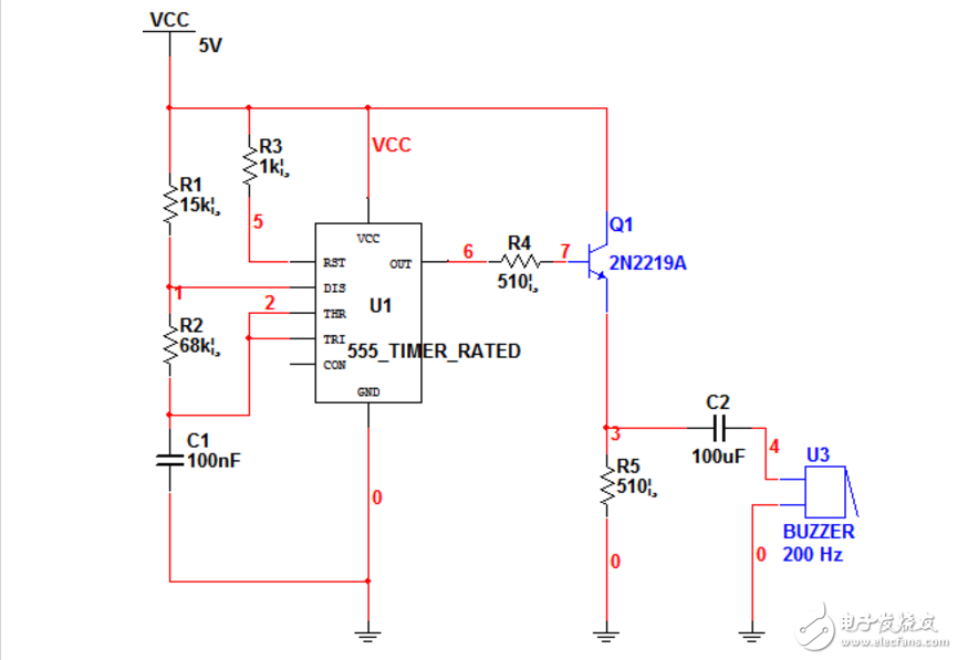
Among them, 555 constitutes a multivibrator, and the oscillation frequency is: f0=1/(R1+2R2)*C*ln2=1.43/(R1+2R2)*C
Its output signal pushes the speaker through the triode. PR is the control signal. When PR is high, the multivibrator works. Otherwise, the circuit stop is no longer working. 3.4 Design of the sequential circuit The timing control circuit is the key to the design of the responder. It has to complete the following three functions: 1 When the moderator puts the control switch to the “start†position, the speaker sounds, the answering circuit and the timing circuit enter the normal answering state. ,
2 When the contestant presses the answer button, the speaker sounds, the answering circuit and the timing circuit stop working.
3 When the set time is up, no one answers, the speaker sounds, and the answering circuit and timing circuit stop working.
According to the above functional requirements and Figure 3.1 and Figure 3.2, the timing control circuit is designed as shown in Figure 3.4:
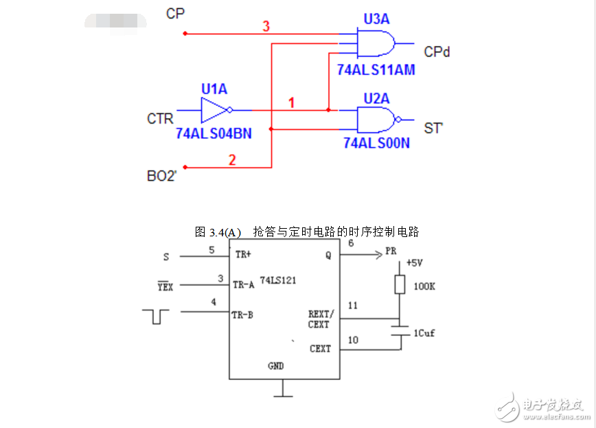
In the figure, the function of the gate G1 is to control the release and prohibition of the clock signal CP, and the function of the gate G2 is to control the input enable terminal ST of the 74LS148. Figure 3-4 (a) works as follows: When the moderator switch is turned from the "clear" position to the "start" position, the output from the 74LS279 in Figure 3-1 is CTR=0, and is inverted by G3. A=1, the clock signal CP from the 555 output can be added to the CPD clock input of the 74LS192, and the timing circuit performs the decrement timing. When the timing time has not expired, the borrow output from the 74LS192 of Figure 3-2 BO2=1, the output of the gate G2 is ST=0, so that the 74LS148 is in the normal working state, thereby realizing the requirement of the function 1. When the player presses the answer button in the timing time, CTR=1, inverting through G3, A=0 , the CP signal is blocked, the timer is in the hold state, the output of the gate G2 is ST=1, the 74LS148 is in the forbidden working state, thereby realizing the requirement of the function 2; when the timing time is up, the borrowing output from the 74LS192 of Fig. 3-2 is obtained. The end BO2=0, the output of the gate G2 is ST=1, the 74LS148 is in the forbidden working state, the player is forbidden to answer, the gate G1 is in the closed state at the same time, the CP signal is blocked, and the timing circuit is in the 00 state, thereby realizing the requirement of the function 3, 74LS121 Used to control the alarm circuit and the time of sounding.
4, the design of the overall circuit4.1 Description of the overall circuit principle
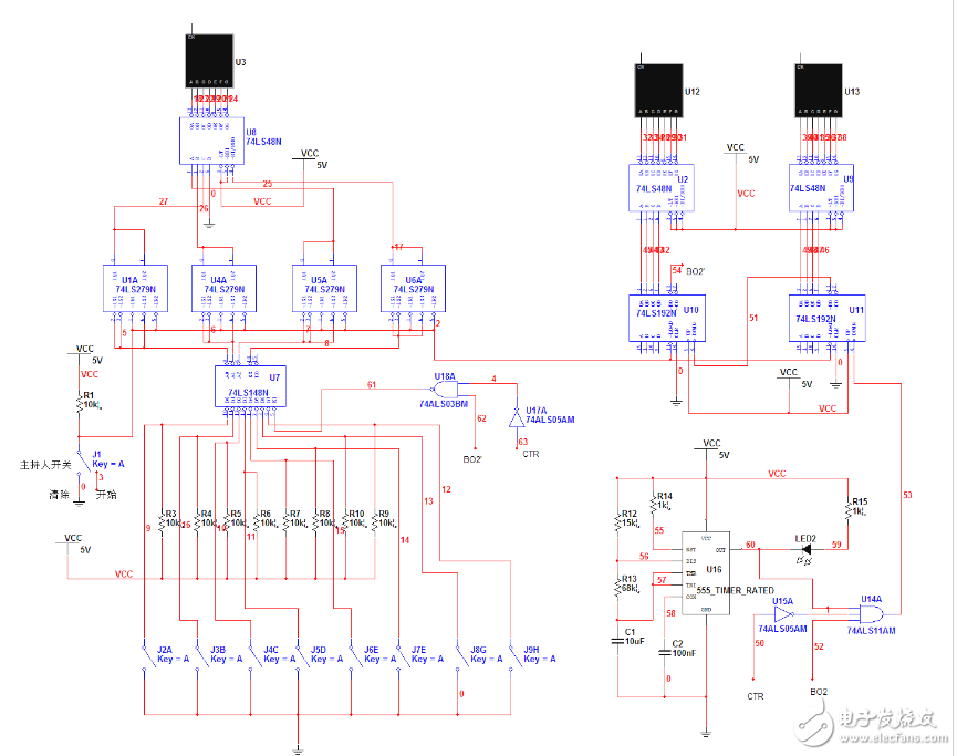
Through the design of the above unit circuit, the whole circuit of the timing answering circuit can be obtained. Strictly according to the guidance of the overall block diagram of the eight-way quiz, combined with the answering circuit of the competition responder, timing circuit, alarm circuit, control circuit to draw the overall circuit!
After the power is turned on, when the host puts the control switch to the “start†position, the speaker sounds, and the answering circuit and the timing circuit enter the normal answering state.
When the contestant presses the answer button, the selector discriminates the player's button sequence and latches the priority responder's number for decoding and decoding the decoding circuit and invalidating other player button operations. After the speaker sounds, the answering circuit and the timing circuit stop working.
When the set answer time is up, no one answers, the speaker sounds, and the answering circuit and the timing circuit stop working.
The overall circuit schematic is as follows:
ZGAR AZ CC Disposable
ZGAR electronic cigarette uses high-tech R&D, food grade disposable pod device and high-quality raw material. All package designs are Original IP. Our designer team is from Hong Kong. We have very high requirements for product quality, flavors taste and packaging design. The E-liquid is imported, materials are food grade, and assembly plant is medical-grade dust-free workshops.
Our products include disposable e-cigarettes, rechargeable e-cigarettes, rechargreable disposable vape pen, and various of flavors of cigarette cartridges. From 600puffs to 5000puffs, ZGAR bar Disposable offer high-tech R&D, E-cigarette improves battery capacity, We offer various of flavors and support customization. And printing designs can be customized. We have our own professional team and competitive quotations for any OEM or ODM works.
We supply OEM rechargeable disposable vape pen,OEM disposable electronic cigarette,ODM disposable vape pen,ODM disposable electronic cigarette,OEM/ODM vape pen e-cigarette,OEM/ODM atomizer device.


Disposable E-cigarette, ODM disposable electronic cigarette, vape pen atomizer , Device E-cig, OEM disposable electronic cigarette
ZGAR INTERNATIONAL TRADING CO., LTD. , https://www.zgarvapepen.com