1:
Siemens
PCS7
System hardware configuration environment
,
Introduction to engineering examples
1) PLC
for
CPU414-5H
redundancy
PLC, CP341(
use
IM153-2), CP341
Main station hardware dog
Dongle ( 6ES7 870-1AA0-0YA0 )
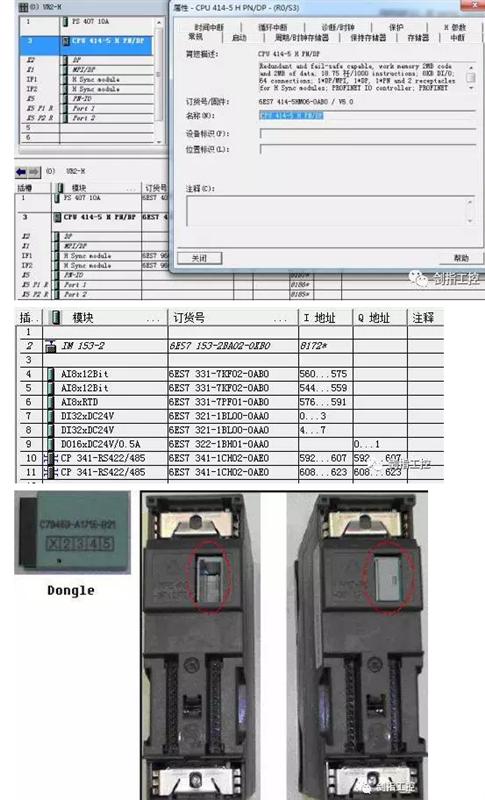
2) CP341
Can be extended multiple
,
Currently used at most
10
One
CP341,
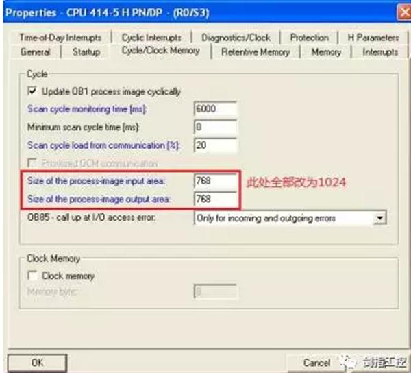
But need to pay attention to
CPU
In the attribute
Cycle/Clock Memory
Process image area
SIZE
by
"768"
Change to bigger
,
Such as
"1024"
2:
Siemens
PCS7
System software configuration environment
1) PCS7 V8.1
Siemens
PCS7
Programming configuration software
2) CP PtP Param V5.1 SP14
Serial communication module driver
3) CP PtP Modbus Master V3.1 SP7 CP341
of
Modbus
Master station driver protocol
,
Must be installed
CP PtP Param V5.1 SP14
Then install this driver
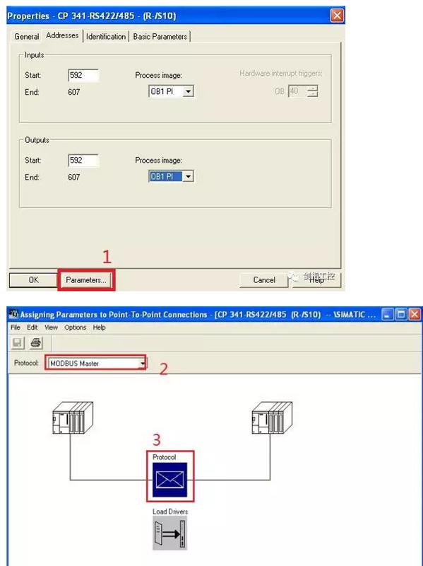
3: CP341
Hardware configuration
1)
Double click to open
CP341
Property dialog
,
Click
"Parameters"
Button
,
Then choose
"Modbus Master";
2)
Double click
Protocol ,
Setting
Modbus
Communication baud rate
,
Stop bit and parity bit
,
As shown
:
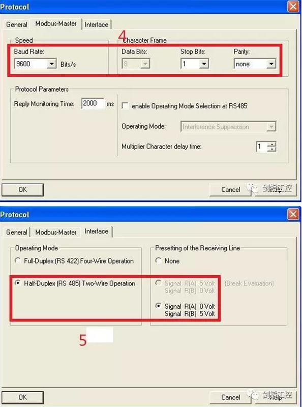
The parameter is set to
: 9600, 8-N-1,
Each slave must be consistent with this
;
3)
Setting the electrical interface
,
Choose to be half duplex
2
line
RS485,
The electrical interface standard of each slave must be consistent with the master station
;
4) Save after configuration is complete
,
And loading,
Redundancy during loadingCPU
Must be set toSTOP
mode.
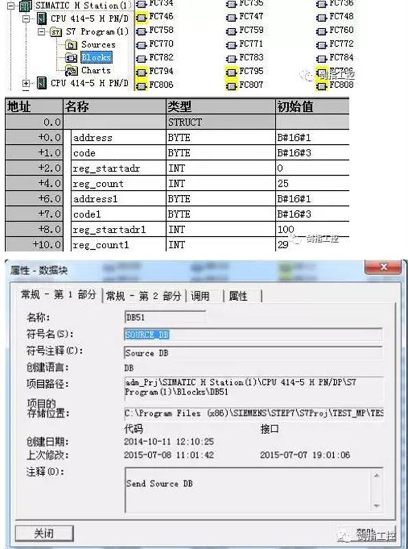
4:
software programming
1)
First you need to manually set up the send and receive data blocks.
DB,
Open component view
,
in
Blocks
Established in
,
For example, the send data block is defined as
DB51,
And define the symbolic name
:SOURCE_DB (
This symbol name must be defined
),
Define after opening the data block
Modbus
Function code data format
,
As shown
: address
Slave address is
1
,
Code
Function code is
3
(Read holding register area as
40001/400001
),
Reg_startadr
The start address of the register is
0
,
Reg_count
Read
25
Register data, which can define multiple different slave addresses in this order
,
Different function codes, different registers.
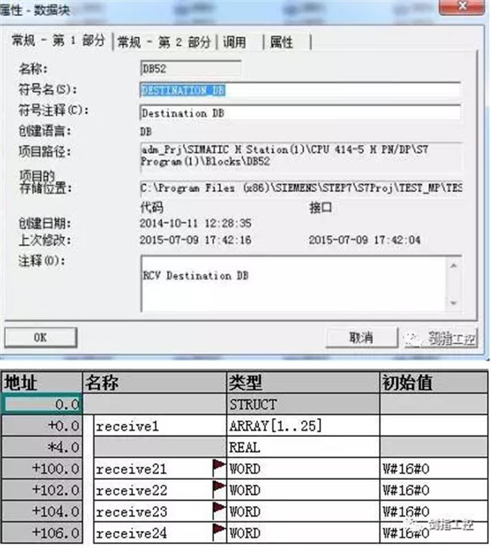
2
) Define the receive data block
DB52
, the symbol name is:
DESTINATION_DB
It is used to store different data from the slave station. When the slave register address is programmed in the slave station, it is better to plan the data that needs to communicate with the master station to the continuous register area, and the data type is preferably kept consistent. If the address is not continuous, Or the data type is different, then you need to manually establish multiple receiving addresses here, as shown in the figure.
Receive1
Defined as an array containing
25
Real-type types, and registers that are not consecutively addressed and have different data types must be created manually.
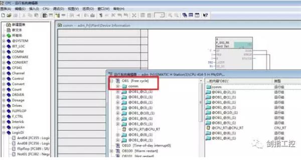
3
) is different from
STEP7
Ladder programming
, PCS7
Used in
CFC
Programming, in the factory view,"
Device Information
Established
CFC
Communication program
"comm",
this
CFC
In the program
OB33
Use the loop mode to train each read function block, when the number is
1
Execution
CFC
Figure
2
The first block in , is
2
Execution chart
2
The second block in the program, and so on;
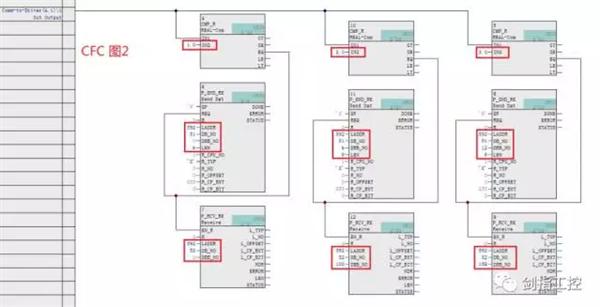
CFC
Figure
2
Transmitting block
FB8
(
P_SND_RK
)
The pin in the definition is as shown below.
LADDRIn the example
592
, refer to the third step
CP341
Hardware configuration;
DBB
_NO
In the example, the first sending block is
0, the second sending block is
6
, the third sending block is
12
, here reference
DB51
Define the address of the part;

CFC
Figure
2
Medium receiving block
FB7
(
P_RCV_RK
)
The pin in the definition is as shown below.
LADDRIn the example
592
,
DB_NO
In the example
DB52
,
DBB
_NO
In the example, the first sending block is
0, the second sending block is
100
, the third sending block is
158
, here reference
DB52
Define part of the address 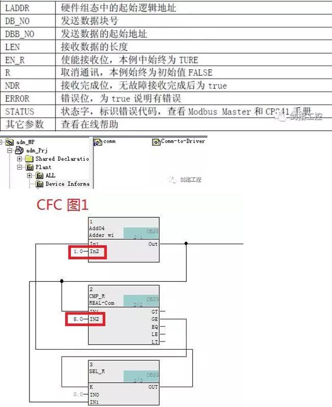
5:
CP341
Troubleshooting
Fault diagnosis is divided into five methods
:1)
by
CP341of
led
Lamp for diagnosis
, SF (
red
)
An error has occurred
(
Such as hardware failure
,
Firmware error
,
Communication line between master and slave is disconnected
)
Or reassigning parameters
; TXD (
green
)
Lights up when sending data,
RXD (
green
)
Lights up when receiving data;
2)
by
FB7with
FB8
Functional block
STATUS
The parameters are diagnosed, and the specific parameter values ​​represent the meanings of the Siemens related documents;
3)
by
CP341Diagnostic buffer for diagnosis;
4)
Diagnostic interrupt indication
CP341failure;
5)
Diagnose through the serial port debugging assistant.
6
:be careful:
1
) use of this
OB33
The communication program with timed interruption has drawbacks, which will prolong the communication time, which may cause packet loss and other phenomena. It needs to be modified to
OB1
Writing communication programs and using
FB8
of
DONE
with
ERROR
Bit activation receives the request and then uses
FB7
of
NDR
with
ERROR
Bit activation next
FB8
, and so on until the last one
FB8
After writing the program, you can pass the run group and the default
OB33
Communication program in
Comm
"Clip to
OB1
In, as shown below:
2
) After writing the program to download
CPU
After that, if it is modified
DB51
or
DB52
Related settings, need to
DB
Initialize, otherwise it will not be able to communicate, the steps are as follows:
turn on
DBPiece
---
"
VIEW
â€
---
by"
Declaration view
Switch
"
Data view
â€
---
"
EDIT
â€
---
"
Initialize Data Block
â€
,
After the change, you need to check if the current data is the required data, and then download the program.
3
)
CP341
Communication
Just pick up
15needle
D
Type connector
4
with
11
Pin, no need to short
2
with
4
Pin and
9
with
11
Pin. When the actual communication cable length is greater than
50
When using meters, add resistance to both ends of the bus.
330
Ohmic termination resistance. make sure
A
,
B
The correct connection of the signal lines.
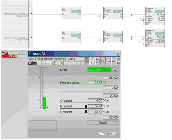
4
)
CP341
If the data read is to be displayed on the screen, except
DB
Upload a small red flag to a single data in the block.
WINCC
Screen, you can also pass
APL
The library's program uploads the data to
WINCC
Screen, the panel generated in this way is more user-friendly, integrating various alarms, high and low limits, trends, etc.
The picture below will
CP341After the data is normalized, upload it to
WINCC
And generate a unified panel
It has a wide range of applications, including power production and power dispatching center, nuclear industry facility operation center, energy production center, traffic operation monitoring center, aerospace mission monitoring center, public safety mission monitoring center, financial trading center, monitoring center, radio and television monitoring center, factory central control room and many other application scenarios. These types of control rooms, Both monitoring center and control center belong to mission critical control environment, which affects the orderly operation of economy and society.Operation method, installation and maintenance of jbkz tank liquid level alarm device. The device is applicable to the monitoring and alarm of high liquid level and overfill cargo tank.
Oil Tanker Cargo Oil Console,Petrochemical Ship Cargo Oil Console,Oil Tank Monitoring Console,Tank Gauge Console Monitor
Taizhou Jiabo Instrument Technology Co., Ltd. , https://www.taizhoujiabo.com