Zhang Wanxu, Liu Lei, Yang Wei, Zhang Weifeng, Yuan Yongde
Keywords: automatic test system; communication mechanism; Vxworks; 1553B bus
Electromechanical systems are an important part of aviation airborne systems. The electromechanical management computer is the control center of the electromechanical system. It undertakes the control and management of the aircraft opening hatch, retractable landing gear, hydraulic and pneumatic actuators, and must ensure accurate and reliable work through accurate testing. Such computers have complex functions and are in mass production. It is not enough to rely solely on technicians and simple general-purpose instruments to complete test verification. Therefore, it needs a set of efficient and reliable automatic testing system to complete.
For the automatic test system, the correct and reliable communication between the automatic test equipment (ATE) and the UUT (unit under test) is the basis for the accurate and efficient operation of the system. Aiming at the characteristics of a mechanical and electrical management computer automatic test system, the communication mechanism between ATE and UUT is studied, and verified in the Vxworks environment through the 1553B bus test.
1 system composition and test plan
1.1 System Composition
The mechanical and electrical management computer automatic test system is mainly used for the mechanical acceptance test and performance verification of a new aircraft mechanical and electrical management. The electromechanical computer consists of a central processing module, an input and output module, a power management module, and a bus control module. According to the requirements of the test task outline, the interfaces and buses such as discrete, analog, 1553B, and ARINC429 must be tested.
The automatic test system consists of an electromechanical computer automatic test equipment (hereinafter referred to as ATE) and an electromechanical management computer (hereinafter referred to as UUT). As shown in Figure 1.
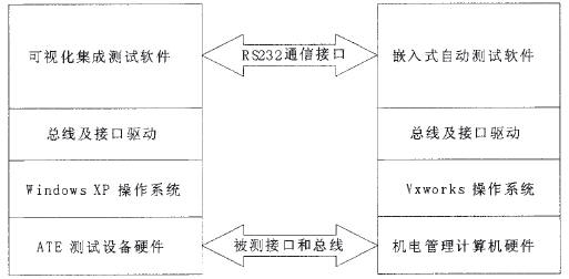
Figure 1 The composition of the automatic test system
The UUT uses Vxworks embedded real-time operating system as the operating system platform. Vxworks is a high-performance and scalable embedded real-time operating system developed by American Wind River. Compared with embedded operating systems such as μC/OS-II and μCLinux, Vxworks has a high-performance microkernel structure and can meet the real-time performance of the system. And reliability requirements.
1.2 Test Plan
In this system, ATE dominates, providing a visual automated test interface that controls the UUT for automated testing. During the test, the UUT receives the test command sent by ATE through the RS232 communication interface and switches to the corresponding test item. According to the requirements of the test item, the ATE sends data or provides incentives through the tested bus or interface. The UUT completes the test task and passes the test information back to the ATE through the serial port. The ATE determines whether the test is successful. After the test is over, the test results are displayed on the ATE and a test report is generated.
2 Test System Communication Mechanism
It is not difficult to see from the test plan that only by ensuring the correctness of the communication between the ATE and the UUT can the testing be performed reliably. The following section studies the communication mechanism of the system.
2.1 Communication Protocol Message Frames
RS232 serial communication protocol is used between ATE and UUT. The provision of a unified message frame guarantees the validity of the message delivery. The message frame is defined as shown in Figure 2.
Figure 2 RS232 communication protocol message frame
The message frame is divided into:
1) Message header (0x55aa): Used to mark the start of the command. After receiving 0x55aa, it is considered to receive a new serial port message.
2) Message number (MsgNum): Used for message matching. In order to avoid confusion in communication, ATE will include a message number when sending a message. When UUT returns ATE, it uses the same message number. After receiving the reply message, ATE judges whether it matches the sent message. If it does not match, it discards the message.
3) Message data length (MsgLength): used to record the length of the data contained in the message. In the message frame, the inherent length of 5 bytes is included, so the actual message length is the data length plus 5.
4) Data 1 (Data 1): Used to store data that needs to be transmitted. Up to 255 bytes of data can be transmitted at a time. During use, ATE and UUT agree on the meaning of the data in the data bits to implement test command transmission. If Datal specifies the bit selection for the module layer, after the UUT receives the ATE serial port message, it can switch to the corresponding module by judging Datal.
5) Checksum: used to verify the correctness of the message. Here it is provided that the message data other than the checksum is summed and inverted as the checksum of the message frame. ATE and UUT will check the checksum after receiving the message to ensure the correctness of the received data.
The message frame has a variable length and is flexible in processing. It has information matching and verification functions, and can pass test commands and data, providing basic guarantees for the reliability of the test system communication.
2.2 Communication handshake mechanism
In order to ensure the reliable establishment of the communication, before the ATE and the UUT communicate, a handshake mechanism is introduced. The handshake mechanism is implemented by sending a specific handshake command word. There are four handshake command words. Based on their mutual correspondence, it is determined whether the handshake is successful. Take the handshake initiated by ATE as an example. First, the ATE sends a one-byte handshake word “0x55†to the serial port. If the UUT exists, it will send the handshake word “0xaa†to the ATE after receiving “0x55â€. After ATE receives “0xaaâ€, it sends “0xac†to UUT, and UUT will reply “0xb7†to ATE. At this point, the handshake between ATE and UUT is successful, and the two can start normal communication. As shown in Figure 3.
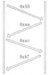
Figure 3 Communication handshake process
Both ATE and UUT can initiate the above handshake process. With the introduction of the handshake mechanism, ATE and UUT can confirm their communication status and ensure that no matter which end is started ahead of time, it can wait for the other end to start up and establish a reliable communication connection.
2.3 Message Receipt and Processing
In the process of communication, it is necessary to receive and process messages in a timely manner. In the Vxworks environment, a task mechanism is adopted to ensure the real-time performance of message reception and processing, avoiding waste of system resources by polling methods, and making the receiving and processing processes relatively independent, facilitating program design and debugging.
The taskSpawn function that calls Vxworks creates two tasks, named cmdRcvTask and cmdDealTask, respectively. cmdRcvTask is responsible for receiving serial messages, checking the format of messages, and storing the correct messages in ReceiveBuf (serial receiving buffer). cmdDealTask ​​is responsible for parsing and processing serial messages.
Both tasks are coordinated by a binary semaphore. Call the semBCreate function to create a binary semaphore that is initially 0. When cmdRcvTask receives the formatted correct serial port message, it releases the semaphore, cmdDealTask ​​obtains the semaphore, changes from the waiting state to the execution state, parses the message, and stores the MsgBuf (message buffer), completing the corresponding instruction processing operation. During the task creation process, the priorities of the two tasks are reasonably assigned. The priority of cmdDealTask ​​is set higher than that of cmdRcvTask. This ensures that cmdDealTask ​​can be executed prior to cmdRcvTask after obtaining the semaphore, reducing the message processing delay. cmdRcvTask and cmdRcvTask program flow chart shown in Figure 4.
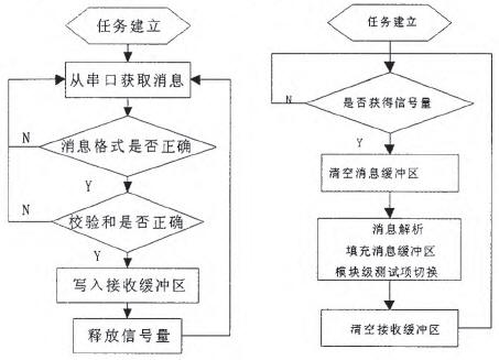
Figure 4 Flowchart for cmdRcvTask and cmdDealTask
The message processing process adopts a hierarchical processing method. According to the characteristics of the test items, the test items are divided into three levels: module level, interface level, and function level. The module layer is divided according to the board module of the electromechanical management computer; the interface layer points to different interfaces of each module; and the function layer implements each interface test function. In the cmdDealTask ​​task, switch module-level test items. In the program design, the switch-case structure is adopted uniformly, and corresponding error handling methods are set in the default item to ensure the fault tolerance of the system. The communication mechanism is verified by the 1553B bus test below.
3 1553B test
The 1555B bus is widely used in avionics systems. The 1553B bus is a centralized time division serial bus with excellent clock synchronization and highly reliable data transmission capabilities. It has three terminal types: bus controller (BC), remote terminal (RT) and bus monitor (BM ). The 1553B bus test is an important task of this automatic test system.
3.1 1553B Bus Testing Software
The UUT 1553B test software is implemented in the Vxworks environment according to the requirements of the communication mechanism. The overall flow chart is shown in Figure 5.
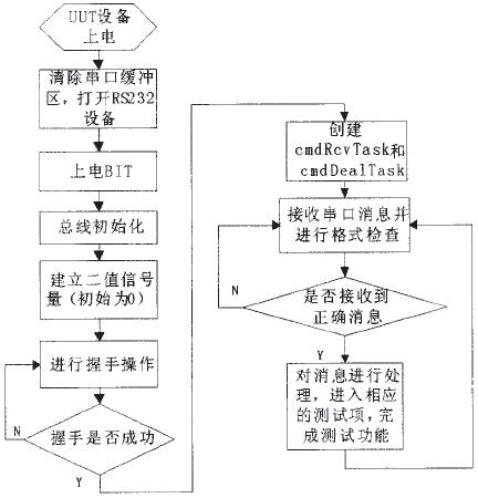
Figure 5 Overall flowchart of the 1553B test
3.2 1553B data transmission test
The data transfer test was performed using the rewind test method. In the test, ATE was used as BC and UUT as RT. Test flow chart shown in Figure 6.
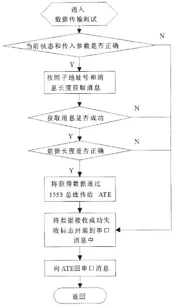
Figure 6 Flowchart of the 1553B data transmission test procedure
During the test, the communication between the ATE and the UUT is reliable, and the UUT can parse the ATE test command correctly to complete the test task with the ATE. The test verifies that the communication mechanism can meet the requirements of automatic testing.
4 Conclusion
This article has carried on the thorough research to the communication mechanism of ATE and UUT in the automatic test system, discusses 3 key technologies of communication protocol message frame, communication handshake mechanism and message receiving and processing in detail, verify the communication mechanism through 1553B bus test in Vxworks environment. . Experiments have verified that this communication mechanism can ensure correct and reliable communication between ATE and UUT, ensuring that the entire system can accurately and efficiently complete the automatic test task, and has certain promotional value.
Temperature And Pressure Compensation Turbine Flowmeter
Temperature and pressure compensation gas Turbine Flowmeter is a kind of velocity flow measurement instrument, in which the turbine speed is the measurement of flow, through mechanical transmission, magneto-electric conversion, forming electrical pulse signals proportional to the flow, making a significant contribution to industrial production and measurement.
Gas turbine flowmeter with temperature and pressure compensation is a kind of velocity flowmeter, which is composed of turbine, bearing, preamplifier and display instrument.
Temperature And Pressure Compensation Turbine Flow Meter,Turbine Flow Meter With Display,High Temperature Oil Flow Meter,Temperature And Pressure Compensation Turbine Meter
Kaifeng Chuangxin Measurement & Control Instrument Co., Ltd. , https://www.kfcxflowmeter.com