The typical circuit of the negative oxygen ion generator composed of IH-3605 type humidity detection special integrated circuit is shown in the figure, which has good effect of purifying air. Safe and reliable, it is suitable for home and office use.
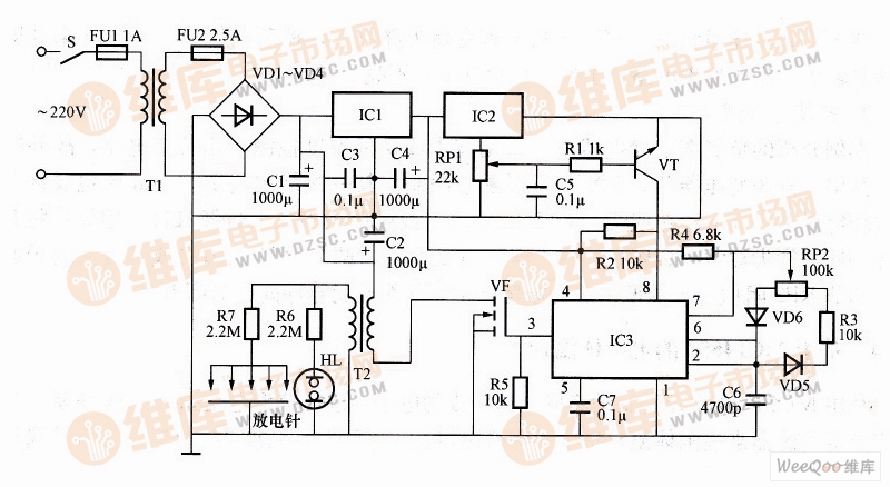
Negative oxygen ion generator circuit constructed by IH-3605
Circuit structure and main component selection: As can be seen from the figure, the negative oxygen ion generator has a power circuit, a humidity detecting circuit, an oscillator and a high voltage generator. The power supply circuit is composed of a power switch S, fuses FU1, FU2, a power transformer T1, rectifier diodes VD1 to VD4, filter capacitors C1 to C4, and a three-terminal voltage regulator integrated circuit IC1. In practical application, T1 often uses 8~10W and secondary voltage is 15V power transformer; VD1~VD4 selects IN4007 type silicon rectifier diode; IC1 selects LM78O5 type three-terminal regulator integrated circuit. The 220V AC voltage is stepped down by T1, VD1~VD4 is rectified, and C1~C3 is filtered to form a DC voltage of about +18V. The voltage is supplied to the VF through the primary winding of the T2; the other is regulated by the LM7805 to +5V, and then supplies power to the subsequent circuits such as the humidity detecting circuit and the oscillator.
The humidity detecting circuit is composed of a humidity detecting dedicated integrated circuit IC2 and a transistor VT, a potentiometer RP1, a resistor RI and a capacitor C5. In practical application, IC2 selects IH-3605 type humidity detection ASIC, which performs signal conditioning inside the circuit, and the output is analog voltage signal. The range of humidity measurement is 0~100%RH. At 25°C, the accuracy is ±2% RH, linearity is ±0.5% RH. VT selects S9014 or 2SC9O14 type silicon NPN transistor; RP1 selects small solid potentiometer or sealed variable resistor.
The oscillator is composed of time base integrated circuit IC3 and potentiometer RP2, diode VD5, VD6 and other peripheral components. In practical applications, IC3 uses NE555 type time base integrated circuit; RP2 also uses small solid potentiometer or sealed variable resistor; VD5 and VD6 select IN4007 type silicon rectifier diode.
The high voltage generator is composed of a field effect transistor VF, a step-up transformer T2, a rectifier diode VD7, resistors R6, R7, a æ°– indicator light HL, and a discharge electrode. In practical applications, VF often uses BUZ380 high-power field effect transistor; VD7 selects 2DL15 high-voltage rectifier tube; HL selects common æ°– indicator light; T2 and discharge electrode can be made by itself.
Working principle: When the circuit is energized, when the relative humidity in the room is small (less than 80%), the output voltage of the second pin of IH-3605 is lower, VT is in the off state, the fourth pin of NE555 is high level, and the oscillator oscillates. The 20kHz oscillation signal is output from the 3rd pin, and the VF is controlled to operate in the switching state. The high voltage pulse of 8~9kV is generated at both ends of the secondary winding of T2, and after being rectified by VD7, the negative oxygen ion is generated through the discharge electrode. The indicator HL lights up.
When the indoor relative humidity is large (more than 80%), in order to prevent the user from getting an electric shock, the IH-3605 pin 2 outputs a high level, so that the VT is in the on state, the NE555 pin 4 is changed to the high level, and the oscillator is stopped. Vibration, NE555 3rd foot has no oscillation signal output, the high voltage generating circuit does not work, the indicator light HL does not light.
Features of Kassel Servo Motor high speed:
1. Constant torque output, low energy loss
2. Lighter, more compact and more efficient
3. With the servo vector algorithm, precise positioning can be achieved
4. Strong environmental adaptability, strong overload capacity, safe and reliable
Kassel servo motor high speed application:
Aerospace satellites, military weapons and equipment, biomedical, extreme environments, automation equipment, automobile assembly
Servo Motor High Speed,Servo Motor High Torque Low Rpm,High Speed High Torque Servo Motor,Parallax High Speed Continuous Rotation Servo
Kassel Machinery (zhejiang) Co., Ltd. , https://www.kasselservo.com