LM1085-ADJ is an output voltage adjustable low-dropout integrated circuit. The output adjustment range is 1.2~15 V. The output voltage can be determined by adjusting the ratio of the resistance ratio of R1 and R2, as shown in the figure.
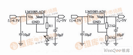
LM1085-ADJ output adjustment and application circuit
Uo=VREF(1+R2/R1)+IADJR2.
Where Uo is the output voltage in V; VREF is the reference voltage, VREF = 1.25 V; IADJ is the reference current and IADJ is 120μA maximum (usually ignored in the calculation).
In practical applications, in order to determine the ratio of the resistance ratio of R1 and R2, R1 is usually fixed and R2 is adjusted to achieve the purpose of regulating the output voltage. Therefore, in practical applications, the above formula can be:
Uo=1.25·(1+R2/R1) There are many types of integrated circuits in the LM108x series. The output currents of different models are different. For example, the output current of the LM1084 is 5 A, and the output current of the 5LM1086 is 1.5 A. The usage is the same as that of the LM1085.
Dongguan Guancheng Precision Plastic Manufacturing Co., Ltd. , https://www.dpowergo.com