0 Preface
Compared with traditional incandescent lamps and fluorescent lamps, LEDs have the characteristics of environmental protection, energy saving, long life, and anti-vibration shock. Therefore, in the context of global energy shortage, LED has become a research hotspot in the lighting industry. Since the quality of the LED driving power supply directly affects the reliability of the LED lighting product, and the LED driving power supply is currently the highest failure rate in the entire LED lighting system, with the continuous expansion of the LED application field, the development is safe, reliable, and efficient. A small-sized, long-life LED drive power supply has become an inevitable trend.
1 LED drive circuit
The light intensity of an LED is proportional to the magnitude of its forward current. A small voltage change across the LED causes a large change in the current flowing through the LED, causing a significant change in light intensity. Therefore, constant current control is usually used for LEDs to keep the luminous intensity constant.
1.1 LED constant current drive circuit topology
For LED circuits of different power levels, different drive circuit topologies should be chosen to achieve a balance between performance and cost.
Low-power LED lighting systems generally do not require power factor correction, so simple topologies such as Primary Side Regulation (PSR) or Buck topology can be used. Among them, PSR technology can minimize the cost of LED drivers. As shown in Figure 1, the circuit only needs to collect the current information of the primary of the transformer to accurately control the LED current at the secondary side, which not only eliminates the output current detection loss, but also eliminates all secondary feedback circuits, reducing cost and improving efficiency. .
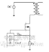
Figure 1 Flyback converter with PSR control technology
For medium-power LED lighting applications, power factor correction is generally required, so a single-stage PFC or a flyback converter using quasi-resonance (QR) technology is generally used. The single-stage LED driving circuit has the advantages of simple structure, few components, low cost, etc., but the output ripple is large, and has an advantage in the application of a medium power LED lighting system with low performance requirements. The basic principle of the quasi-resonant technology is to use the capacitance between the two ends of the MOSFET (parasitic capacitance or external capacitance) and the resonance of the primary side of the transformer to drive the load, and control the near zero voltage of the switching tube by detecting the valley voltage at both ends of the switching device in real time. , thereby reducing the switching losses of the MOSFET, improving the efficiency of the converter, while reducing EMI noise, as shown in Figure 2.
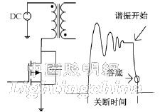
Figure 2: Flyback transformation using QR technique
1.1.3 High-power LED lighting systems generally use a two-stage PFC or LLC topology. The two-stage PFC has better performance due to the separate primary PFC, but the cost is relatively high. The LED drive circuit using LLC resonant conversion (shown in Figure 3) has many advantages, such as high switching operating frequency and switching loss. Small, allowable input voltage range, high efficiency, light weight, small size, low EMI noise, low switching stress, etc.
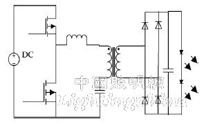
Figure 3 LED driver circuit based on LLC converter
1.2 De-electrolytic capacitor LED driver circuit solution
LED lighting is mostly powered by mains, but LEDs require DC drive, so a rectifier module is required in the circuit. Usually, in order to obtain a specified PF value, it is also necessary to add a PFC circuit. Because the input power is pulsating and the output power is constant, a large capacitance electrolytic capacitor must be used to balance the instantaneous power difference across the input and output. The presence of an electrolytic capacitor reduces the life of the LED drive circuit. If the electrolytic capacitor is simply removed, the output current will be greatly pulsated, and the PF of the circuit will be lower. If the electromagnetic energy storage is used instead of the capacitor, the circuit will be bulky. Therefore, other de-electrolytic capacitor LED drivers are studied. The circuit scheme is necessary.
Based on the consideration of the smaller ripple current, which can be used to drive the LED, the LC filter circuit is added on the output side while the electrolytic capacitor is removed, and the 3rd and 5th harmonic currents are injected into the input current to achieve the power factor. It can reduce the peak-to-average ratio of the LED current. However, this method will cause LED flicker because the output current contains twice the AC current of the grid frequency. Working under the flashing light source for a long time will increase the burden on the eyes and even cause eye damage.
Another scheme is shown in Figure 4. The design of the circuit is to control the current ib flowing through the bidirectional Buck-Boost auxiliary loop equal to twice the AC component of the grid frequency in i0, thereby indirectly controlling the current flow through the LED. Constant to avoid LED flashing. However, this solution is less efficient due to the need to add multiple additional devices.
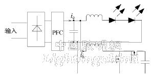
Figure 4: Electroless capacitor LED driver circuit using auxiliary circuit
In [6], a sinusoidal current or a square wave current with a ratio of peak to average of less than 1.4 is used to drive the LED, and a reference signal is generated by a sinusoidal current generating circuit or a square wave current generating circuit, thereby obtaining a desired current signal for direct use. The LED [6] is driven and the input side can achieve a very high power factor, but the control method is complicated. The LED drive scheme of electroless capacitors still has many shortcomings, such as complicated system control, high power factor, slow system startup, and sensitivity to lightning strikes. Currently, it is only used in small and medium power LED lighting systems. Further research is needed for its wider application.
2 LED current sharing technology
In order to ensure the uniform brightness of multiple LEDs, it is usually connected in series. The number of LEDs connected in series is limited by the LED driving voltage, so the series-parallel connection is generally used in applications requiring more LEDs. However, due to the different VI characteristics of different LED strings, simply connecting them in parallel creates a problem of multiple paths of uneven current. Aiming at the current sharing of multiple LEDs, there are many kinds of current sharing methods, which can be roughly divided into active current sharing and passive current sharing.
2.1 Active current sharing
Active current sharing is the use of active devices such as switching tubes plus a certain control circuit to form a current regulator to achieve current control. The current regulator has both linear and switching modes of operation. The linear mode current regulator is subjected to the voltage difference between the input voltage and the LED turn-on voltage drop, and the input voltage is set according to the maximum on-voltage drop of the LED. Therefore, the regulator is inefficient, even if adaptive. The control method also does not significantly improve efficiency. This scheme is only suitable for low-power lighting systems; the switch-mode current regulator uses a DC-DC converter to regulate the current of each channel, which is more efficient, but each path needs A DC-DC converter, so the cost is high for multiple outputs, and the system is huge.
2.2 Passive current sharing
Passive current sharing refers to the use of passive devices to achieve current sharing control. Figure 5 shows a scheme for realizing multiple current sharing using a current sharing transformer. It utilizes the relationship between the coupled inductors so that a change in one current can be coupled to the other to achieve current sharing. However, when multiple outputs are required, a large number of current sharing transformers are required, and the deviation of the inductance value of the transformer and the deviation of the output voltage all affect the accuracy of the current sharing.
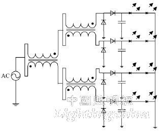
Figure 5 Transformer current sharing
For safety reasons, LED drivers usually require electrical isolation of the input and output, so many times you need to consider isolated LED driver circuits, such as half-bridge, full-bridge and other circuits. Figure 6 shows a method of using balanced capacitor current sharing. It uses the characteristics of positive and negative alternate output of the secondary side of the transformer to realize the two-way current sharing by using the stability characteristics of the capacitor in the loop at steady state.
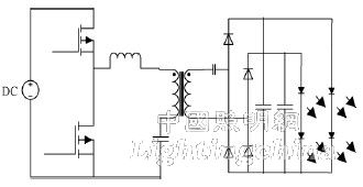
Figure 6: Capacitor current sharing circuit based on LLC converter
In order to realize the simultaneous current sharing of 2N channels, a scheme of connecting a plurality of transformer primary sides in series may be adopted, but it requires the parameters of the transformer magnetizing inductance to be completely identical, otherwise the current sharing effect may be affected. For this reason, in the case of multiple outputs, a scheme of combining the coupled inductor current sharing with the capacitor current sharing can be adopted, thereby realizing 2N LED current sharing, as shown in FIG.
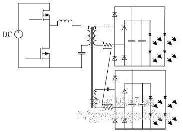
Figure 7: Capacitor-coupled inductor current sharing circuit based on LLC converter
In the above-mentioned current main current sharing scheme, although the passive scheme is simple, the current sharing accuracy cannot be guaranteed because the feedback control is not used, and the current sharing effect is susceptible to the variation of the device parameters; and the active scheme adopts the feedback control. It can precisely control each current, but requires more components, the control circuit is more complicated, the cost is higher, and the introduced active device will make the system less efficient.
3 Conclusion
In order to make the new generation of green energy-saving light source LEDs widely used in the field of general lighting, it is very important to design efficient and stable LED driving circuits. For different application environments, a reasonable driving method should be adopted to ensure reliable operation of the LED, and at the same time, efforts should be made to overcome the life limit imposed by the electrolytic capacitor, so that the LED lighting is truly on the right track.
Edit: Cedar
Packages For Fiber Optic Communication,Optical Housings,Optical Communication Component,Optical Communication Fine Tube
Shaanxi Xinlong Metal Electro-mechanical Co., Ltd. , https://www.cnxlalloyproduct.com