The realization of the touch key is mainly by detecting the number of oscillations of the RC oscillating circuit built on the board-level system within a fixed time. If the number of oscillations changes significantly, it is judged as the touch state. Then the number of oscillations is mainly determined by the value of RC. In the system, the R value is fixed, and the capacitor C is the sensor in the system, which is a copper clad piece of PCB layout size and finger size. It forms a small capacitance (approximately 10pF) with the surrounding formation. When a finger approaches, it changes its dielectric constant, ![]() As a result, the capacitance value changes, and thus the number of oscillations changes. As shown in Figure 1
As a result, the capacitance value changes, and thus the number of oscillations changes. As shown in Figure 1
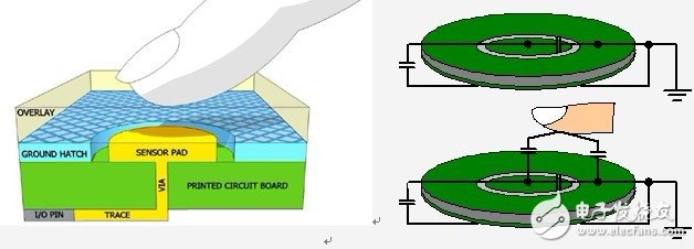
figure 1
From an implementation point of view, to realize the touch function requires an RC oscillation comparison network, a comparator and a counter. The MSP430 has this kind of resources, and its pin leakage current is very small, which is very suitable for the function of touching buttons. At present, there are mainly a method for detecting the RC charge and discharge time (RC) and a method for detecting the number of RC oscillations, namely relaxation oscillation (RO). From the perspective of current application, the RO method has better stability and anti-interference ability. The principle is shown in Figure 2.

figure 2
MSP430's built-in comparator, external impulse discharge resistor Rc and inductive capacitor Csensor together form a relaxation oscillator structure. The sensing capacitor Csensor is the tuning component of this oscillator. Any change in Csensor will change the resonance frequency of the relaxation oscillator accordingly. We use the timer A built in the MSP430 to sample the oscillation frequency so that we can detect the change in Csensor.
Touch button based on MSP430Two
The principle of touch buttons has already been mentioned in the first article. This article mainly introduces how to use MSP430 to construct touch buttons.
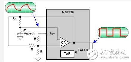
figure 1
This picture 1 has been mentioned in the previous chapter. For Px.y in the figure is high, the positive terminal of the comparator is high, and the Csensor is charged until the negative terminal of the comparator is high, and the output of the comparator is reversed to low, then the Csensor starts to discharge, and so continues to oscillate. The output of the comparator is a square wave signal, which is counted by TImerA. By comparing the changes in the number of oscillations in a fixed time window to determine whether there is a touch action. The figure below shows the relationship between the time window and the number of oscillations.

figure 2
Smart Uv Printer,3D Photo Printer,3D Emboss Back Skin Printer,3D Relief Back Film Printer
Shenzhen TUOLI Electronic Technology Co., Ltd. , https://www.hydrogelprotector.com