On the basis of Freescale's SMAC protocol framework, an effective method for forming a ZigBee star network is proposed. This paper gives the hardware composition of the network nodes, and analyzes the software design ideas of the network formation in detail; the wireless network is applied to a textile workshop line transformation project, which solves the difficulty of walking between multiple devices under the original workshop layout The problem of line greatly reduces the cost.
introduction
ZigBee technology is a recently developed short-range wireless communication technology. It has low power consumption, low cost, and easy application. It works in the 2.4 GHz frequency band and uses spread spectrum technology. ZigBee is considered by the industry as the wireless technology most likely to be used in industrial monitoring, sensor networks, home monitoring, security systems and other fields. At present, there are many companies on the market that provide ZigBee products, but the price of the large and versatile ZigBee wireless communication system (including the protocol stack) is relatively expensive. The separate ZigBee module does not have the functions of network communication and node independent addition. To a large extent, it limits the flexibility and extensiveness of ZigBee product applications. Based on the software architecture of Freescale's SMAC protocol package, this article uses MC13192 RF transceiver to successfully build a ZigBee star network. In this network, multiple communication nodes can freely enter the network to achieve reliable transmission of data packets in the network. And each node has good scalability in software and hardware, and can access multi-sensor signal network communication.
1 Structure of star network
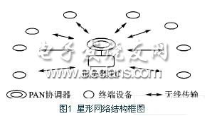
The star network structure is shown in Figure 1. All terminal devices communicate with a unique central control device (PAN coordinator), and communication between terminal devices is achieved by the forwarding of the PAN coordinator. The network terminal equipment is either the starting point of data transmission or the end point of data transmission.
There must be a PAN coordinator in the network, which initializes the various attributes of the network and establishes the descriptor table of the coordinator before the network is established, and then waits for the terminal device to enter the network. Since there is no router in the star network, only a maximum of 255 terminal devices can be allowed to join the network. When the terminal device sends data, it must first send the data packet to the PAN coordinator. The PAN coordinator queries the neighbor device list according to the source address field in the data packet to determine whether the terminal device is already on the network. When the device exists in the neighbor device list, it means that the terminal device is already in the network, and then the PAN coordinator analyzes the data packet. If the destination address field of the data packet is the PAN coordinator, the PAN coordinator receives the data packet and processes its information field; if the destination address field of the data packet is another terminal device, the PAN coordinator determines whether Forward data packets for terminal devices. In a star network, the PAN coordinator is powered by an uninterruptible power supply (UPS), while other devices are powered by batteries.
2 Hardware design of network nodes
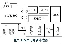
Regardless of whether it is a coordinator or a terminal device, the hardware design is generally the same, but the peripheral circuit needs to be slightly modified according to different environments. In the working mode, the amount of data transmitted by the network node is very small, so the receiving / transmitting time of the signal is extremely short; while in the non-working mode, the network node is in the sleep mode. Moreover, the device search, sleep activation, and channel access delay (30 ms, 15 ms, and 15 ms, respectively) are very short, making the network node power consumption extremely low and very power-saving. Figure 2 shows the basic block diagram of the hardware design.
2.1 Central Processing Unit
MCU selects Freescale's 8-bit microcontroller MC9S08GT60, the internal bus frequency is up to 20 MHz, and it can fully support high real-time radio frequency modules. 60 KB of Flash is enough to accommodate the ZigBee protocol stack. The 10-bit A / D conversion module is used for data collection of sensor signals. Two serial communication interfaces (SCI) are used to communicate with the host computer. The serial peripheral interface (SPI) is used for data transfer between the MCU and the RF module. Each function module can apply to the MCU for an interrupt after the action is completed, so CPU intervention is rarely required.
2.2 RF communication module
The radio frequency communication module uses Freescale's MC13192 RF transceiver, which contains a complete IEEE 802.15.4 standard physical layer (PHY) modem to support the point-to-point, star and mesh networks specified by the IEEE 802.15.4 standard Communication. In communication, when the packet error rate of this transceiver is 1.0%, the output power is less than -92 dBm (typical value), which is much lower than the -85 dBm specified in the IEEE 802.15.4 standard.
2.3 Interface between MCU and RF module
The control and data transfer of the MC13192 relies on a 4-wire serial peripheral interface (SPI). Its four interface signals are MOSI, MISO, CE, and SPICLK. The main control MCU exits the sleep mode or the sleep mode through the control signal ATTN, resets the transceiver through RST, controls data transmission and reception through RXTXEN, or forces the transceiver to enter idle mode. The schematic diagram of the interface is shown in Figure 3.

4.2Mm Ribbon Connector,Strip Connectors,Strip Terminal,Strip Connector
YUEQING WEIMAI ELECTRONICS CO.,LTD , https://www.weimaiwafer.com