Modern production demands have led to the development of process control to the requirements of multiple inputs and multiple outputs, as well as the increasing control dispersion and management concentration of modern industries. Distributed control systems (dcs) have emerged. In the current situation that foreign fieldbus equipment and DCS are very expensive, the transformation of the distribution system of state-owned enterprises can only take the road of their own characteristics. In view of the above problems and application requirements, this paper uses smart meters as the field control equipment to study the related technologies in DCS and its applications, and proposes a design scheme of multi-intelligent instrument control system, and builds a multi-intelligent instrument DCS experimental system. Considering the actual needs of the experiment, the controlled object model and the computer monitoring system software were designed. The experimental system consists of a PC, a smart meter, a serial communication interface card, an RS-485 bus, and a controlled object model system.
1. Architecture of multi-intelligent instrument control system
1.1 General DCS Architecture
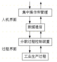
The development of process computer control systems since the mid-1970s has entered a period of development of distributed control systems (DCS) characterized by the use of 4C technology (computer, communication, control, CRT display technology). From the system structure analysis DCS can be divided into three basic parts: the distributed process control device part, the centralized operation and management system part and the communication system part. The relationship between the three parts is shown in Figure 1.
Functional stratification is a system feature of DCS, which fully reflects the characteristics of distributed control and centralized management of distributed control systems. According to the function layering method, the multi-intelligent instrument control system can be divided into a field control station, a process control station, a control level, and a production management station.
1.2 Multi-intelligent instrument control system architecture

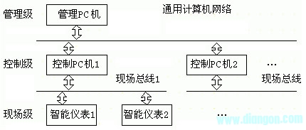
(1) Overall structure As mentioned above, the multi-intelligent instrument control system is oriented to the needs of domestic SMEs for technological transformation. Therefore, after integrating the functions of the general DCS layers, we propose the network structure of the multi-intelligent instrument control system, such as Figure 2 shows.
The field-level components are mainly composed of smart meters, and the control PCs can be composed of industrial computers or ordinary PCs. The fieldbus connection is used between the smart meter and the control PC. The fieldbus protocol should be designed according to the requirements of the control and the characteristics of the smart meter. The management level component is mainly composed of a commercial PC or other computer, and constitutes a management information system MIS (Management Information System). A general computer network connection is used between the management PC and the control PC, and the specific types thereof can be determined according to the requirements of the composition of the MIS system.

(2) The emergence of the built-in microprocessor of the smart meter has made the intelligent instrument fundamentally change in the design method, circuit structure and function operation compared with the traditional instrument. In the smart meter, except for the adjustment function, which is almost completely realized by the microprocessor, the microprocessor is the core and works in an orderly manner under the control of the instrument software. In the multi-intelligent instrument control system, the information exchanged between the smart meter and the control PC can be divided into: measured value; set value; control quantity; status parameter (one is the value reflecting the working condition or production status of the smart meter or 0) /1 logic value, the second is the setting of the working status and parameters of the smart meter, the most typical is the PID parameter setting).
(3) Control PC Control PC is mainly used to realize centralized operation and advanced control. It is a bridge between decentralized control and centralized management of PC. It generally completes display and printing, control management and operation, and system configuration configuration. Features.
(4) The management level must achieve higher level of control and management in order to achieve the above control objectives. Modern enterprises use the MIS system to achieve.
(5) Fieldbus intelligent instrumentation and fieldbus technology are inseparable and complementary. At present, domestic smart meters generally use general-purpose single-chip microcomputers such as MCS-51 series. Therefore, considering the technical realization, economy and production, when using many fieldbus standards for technical transformation of state-owned enterprises, it is better to adopt RS-485 bus. Multi-intelligent instrument control system uses RS-485 bus as communication protocol. Physical transmission medium.
2. Communication protocol of multi-intelligent instrument control system
The intelligent instrument communication function is the basis of the realization of the intelligent instrument DCS system. Based on some existing protocols, we have rationally designed the communication function hardware and software, and proposed a multi-intelligent instrument control system protocol. The overall communication strategy is reserved. The protocol, ie time is divided into time slices, and each smart meter communicates with the host using a pre-reserved time slice. The network level model of the fieldbus draws on the OSI seven-layer protocol and is partially extended, focusing on industrial applications, and constitutes the communication network of the industrial site. The specific network specification in this design adopts the application layer, network layer, data link layer, and physical layer in the OSI protocol. At the physical layer, the transmission medium of the system field bus uses an RS-485 twisted pair. At the data link layer, its main functions are: assembly and decomposition of information frames, error control and processing. The baud rate adopts the standard 1200, 2400, 4800, and 9600, which can be selected according to the system design requirements; the transmission frame adopts the standard UART format.
On the multi-intelligent instrument control system field bus, the transmission frame can be divided into an address frame and a data frame, the difference being that the ninth data bit in the address frame is "1". The ninth data bit in the data frame is "0", and the error check uses the CRC check. At the network layer, the fieldbus is a network in which multiple nodes are collinear, and the management of the network layer is performed by the control PC. The address frame is sent by the control PC to wake up a smart meter on the bus to establish communication with it. The smart meter only starts the communication process after receiving the address frame containing the specific data bit (usually its instrument address number). . The communication process of the smart meter begins by returning a data frame containing a specific data bit (meter address) to the control PC; upon receiving the data frame, the control PC confirms establishment of communication with the smart meter. Controlling the communication between the PC and the smart meter is the process of exchanging information into multiple frames.
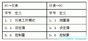
At the application layer, for a multi-intelligent instrument control system, the application layer protocol is a definition of a multiframe that controls the mutual transmission of information between a PC and a smart meter. The application layer protocol is shown in Table 1:
Table 1 Application Layer Protocol
The interface conversion circuit between the PC interface and the fieldbus of the smart meter DCS experimental system uses the PCL-743/745 serial communication interface card produced by Advantech. Each interface card has two RS-485 serial communication ports, each with a Universal Asynchronous Receiver Transmitter (UART) with a 16-byte first-in, first-out (FIFO) buffer. It buffers the data into a 16-byte packet before placing the data on the bus, which greatly reduces the CPU load and avoids data loss when the system is busy or cannot handle interrupts in time. This is for Windows operating systems. The high-speed serial I/O port is especially important. The I/O base address and interrupt request are set by some jumpers on the card before the interface card is installed. The communication function of the PCL-743/745 serial communication interface card is realized by reading and writing operations to its internal registers.
3. Control programming and communication software design for controlling PC communication function
Control the communication function of the PC with Visual C++6.0 to compile a communication thread ThreadProcForComm (LPVOIDparam) implementation, this communication thread only completes the data transceiving and processing, including flag, data_tra, data_rec, address and other variables, flag is the communication success or not flag, Data_tra is the send data buffer array, data_rec is the receive data buffer array, and address is the smart meter address array.
Monitoring software preparation should complete the following functions: monitoring and operation, printing functions and storage functions. Throughout the software, the implementation of all control functions is done by the control subfunction. For the modification of the set value and the control amount and the change of the control mode, the software provides a Visual C++ class, which has three member functions SettingValueModify(inth, WORDnew), the parameter h represents the meter number, and the new represents the newly set value; Algorithm interface, the software also provides a Visual C++ class, this class has two member functions Data_in (measureIn[], setpoint[]) and Data_out(controlOut[]), the former passes the measured value and set value, the latter Send the control value. measureIn[], setpoint[], and controlOut[] represent arrays of measured values, setpoints, and control values, respectively, which are global static variables. Users can freely write specific control algorithms in this class. As for the design of the storage and printing functions of the software, it will not be introduced here.
4, examples
This design is based on the SEU-211 intelligent temperature controller to improve the design of the USTS-100 smart meter. SEU-211 intelligent temperature controller is also an intelligent control instrument for DCS applications. Its control object is electric heating furnace, using thermocouple as temperature sensor; the input of the meter is thermocouple signal, output thyristor trigger signal; communication function, communication The protocol is based on RS-485 and adopts the structure of transmitting data frames after address call/response. In the design of the USTS-100 smart meter, the hardware has mainly made the following improvements: (1) The input/output signals of the USTS-100 can be matched with standard voltage and current signals, and the input and output circuits of various signals are integrated to form a capable The input and output circuits of different circuit structures and circuit parameters are taken into consideration to enhance their versatility. The controlled object model system is also designed, so that the characteristics of different industrial process control objects can be realized by software, and the application capability of the DCS system can be enhanced. (2) In order to implement complex control algorithms, the instrument microcomputer reserves a power-down protection memory that can be expanded to 32 KB, which can realize arbitrary configuration of program space and data space. (3) The core device of the level conversion of the communication part is changed to the MAX485 with better performance. Therefore, the improvement of the hardware circuit is mainly to enhance the adaptability of the instrument, and the improvement of the communication function is mainly focused on the software.
In order to take into account the strict sequence of the internal measurement and control body of the instrument and the randomness of the communication function, the instrument software design draws on the multi-tasking operating system module, and sets the task list and task trigger/start mechanism, thus ensuring the modules. Strict sequence requirements; at the same time, the communication function is also decomposed into small modules, and the data buffer area is set and sent, and the task trigger mechanism and task are determined according to the relationship between each communication function module and each measurement control function module. Startup mechanism. The design details of this part are trivial and will not be repeated here.
5 Conclusion
This paper aims at the industrial production automation technology transformation of state-owned enterprises. According to the characteristics of intelligent instrument networking, it is proposed to use the control PC to connect with smart meters through RS-485 bus to form a multi-intelligent instrument control system. Based on the representative fieldbus protocol, the communication protocol of multi-intelligent instrument control system is proposed, the application software is compiled, and the USTS-100 temperature controller with this communication function is designed to form multiple intelligences. A practical system for the instrument control system completed a targeted experiment. The experiment proves that the experimental system is running well and can complete various complicated control experiments. This research will help to improve the research and application level of domestic smart meters, expand its application fields, and adapt to the technological transformation needs of domestic small and medium-sized enterprises, so it has theoretical significance and practical value.
KNL5-100 Residual Current Circuit Breaker
KNL5-100 Moulded Case Circuit Breaker is MCCB , How to select good Molded Case Circuit Breaker suppliers? Korlen electric is your first choice. All moulded Case Circuit Breakers pass the CE.CB.SEMKO.SIRIM etc. Certificates.
Moulded Case Circuit Breaker /MCCB can be used to distribute electric power and protect power equipment against overload and short-current, and can change the circuit and start motor infrequently. The application of Moulded Case Circuit Breaker /MCCB is industrial.
Korlen electric also provide Miniature Circuit Breaker /MCB. Residual Current Circuit Breaker /RCCB. RCBO. Led light and so on .
KNL5-100 Molded Case Circuit Breaker,KNL5-100 Small Size Molded Case Circuit Breaker,KNL5-100 Electrical Molded Case Circuit Breaker,KNL5-100 Automatic Molded Case Circuit Breaker
Wenzhou Korlen Electric Appliances Co., Ltd. , https://www.korlen-electric.com