Today's radio designs and other wireless communication devices consume less and less power and take up less and less physical space, so the area of ​​the board that can be used for heat dissipation is getting smaller. In addition, these systems are being deployed in more extreme environmental conditions where only passive heat dissipation is used, resulting in the need for very reliable ICs that can withstand large temperature changes. As the scalability of the system's output power increases, a new equally scalable RF driver amplifier is needed. To meet all of these goals, Analog Devices has introduced the ADL5324 1/2 W SOT-89 RF driver amplifier.
The ADL5324 features a dynamically adjustable bias circuit that allows for custom OIP3 and P1dB performance from 3.3 to 5 V without the need for an external bias resistor. This feature allows the designer to tailor the performance of the driver amplifier to the specific needs of the design. The adjustable bias also allows the driver to be dynamically biased to save power when the driver amplifier does not require full performance, such as system standby mode. This scalability reduces the evaluation and inventory of multiple driver amplifiers required for different output power requirements (from 25 to 29 dBm output power level). The ADL5324 is rated for operation from -40°C to +105°C, ensuring the reliability of higher temperature designs such as power amplifiers. The 1/2 W driver amplifier also covers a wide frequency range of 400 to 4000 MHz, requiring only a few external components to be adjusted to a specific frequency band over this wide range. This high-performance wideband RF driver amplifier is ideal for a wide range of wired and wireless applications, including mobile communications infrastructure, ISM band power amplifiers, defense equipment and instrumentation.
The ADL5324 GaAs HBT 1/2 W driver amplifier consumes 133 mA of low 5 V to provide optimum performance at 2140 MHz with an OIP3 of 43.1 dBm, a P1dB of 29.1 dBm, a gain of 14.6 dB and a low noise figure of 3.8 dB. When the bias voltage drops to 3.3 V, the driver consumes only 62 mA, the OIP3 at 2140 MHz provides 34.4 dBm, P1dB is 25.3 dBm, the gain is 13.6 dB, and the low noise figure is 3.2 dB. The driver amplifier can also be biased at any point from 3.3 to 5 V to meet the performance requirements of a system between 3.3 or 5 V. This feature creates an opportunity for the dynamic biasing of the driver amplifier, where a variable supply is used to achieve a full 5 V bias in large signal conditions and then reduce the supply voltage when the signal level is small and low power is acceptable. (see picture 1).
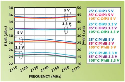
Figure 1: ADL5324 OIP3 and P1dB vs. VCC and temperature show that a 3.3 to 5 V bias can meet system requirements.
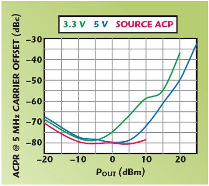
Figure 2: ADL5324 ACPR vs. output power and Vcc (3GPP 3.5 TM1-64 at 2.14 GHz) show that the -55 dBc ACPR can be reduced to -15 dBm at 3.3 V bias.
The ADL5324 also offers excellent ACPR and output power and bias voltage advantages. The driver delivers greater than 17 dBm of output power at 2140 MHz while achieving -55 dBc ACPR at 5 V. If the bias voltage is reduced to 3.3 V, the -55 dBc ACPR output power can be reduced to a minimum of 15 dBm (see Figure 2).
The ADL5324 eliminates complex external tuning and further simplifies RF design. The driver's amplifier inputs and outputs use only 50 V lines and do not require a bias resistor. The ADL5324 requires only one shunt capacitor at the input and only one shunt capacitor at the output for frequency tuning. Normally, AC coupling capacitors and DC bias choke inductors are required, as well as standard bypass capacitors for DC offset traces.
The design and packaging of the ADL5324 also simplifies thermal issues. The driver has an optimum current consumption of 5 V 133 mA, which reduces the amount of heat generated. The 3.3 V current consumption can be reduced to 62 mA, which further reduces the amount of heat generated. The standard SOT-89 package has a large ground paddle that provides an efficient heat transfer path for the driver amplifier. The data sheet shows the recommended board land pattern with increased heat transfer holes to further improve the heat transfer of the driver amplifier. This helps the drive operate over a safe operating temperature range without forced air cooling, and the drive specifies a wide operating temperature range of -40°C to +105°C. The drive amplifier is rated for an ESD rating of ±3 kV (HBM, Class 2), which makes it equally robust in high volume manufacturing environments.
Another way ADI can help improve RF design is the information provided in the ADL5324 data sheet. The data provided includes key parameter changes with temperature (from -40 ° C to +105 ° C), supply voltage (from 3.3 to 5 V), and operating frequency (from 400 to 4000 MHz), which reduces the qualification review for designers time. The reduction in qualification review time can significantly speed up the time-to-market of the project. A comprehensive data sheet also helps designers accurately determine the lowest achievable power consumption to meet their specific application performance goals.
ADI has improved RF design in a number of ways through innovative circuit design, simplified tuning requirements, and detailed data sheet information. These attributes help RF designers quickly get to market with solutions for smaller, lower power systems.
Capacitor for Electric Furnace
Capacitor For Electric Furnace, commonly referred to as capacitors, are capacitors, expressed in the letter C.Definition 1: a capacitor, as the name implies, is a "charging vessel", a device that holds charge.Capacitor.Capacitors are one of the most widely used electronic components in electronic equipment. They are widely used in the fields of interleaving, coupling, bypass, filtering, tuning circuit, energy conversion and control.Definition 2: a capacitor consisting of any two conductors (including wires) that are insulated from each other and are very close together.
Components Capacitors,High Voltage Capacitors,Low Frequency Capacitor,Water Pump Capacitor,Capacitor for Electric Furnace
YANGZHOU POSITIONING TECH CO., LTD. , https://www.cnchipmicro.com