I. Introduction
This article refers to the address: http://
The hybrid vehicle uses a conventional internal combustion engine and an electric motor as a power source to start the vehicle by mixing two systems of heat energy and electric power to save fuel and reduce exhaust pollution. Hybrid vehicles In addition to engine, electric motor, battery and other unit technologies, the important technology is the electronic control technology of each system and the power system optimization and control technology of the whole vehicle. This article focuses on the application of the WEINVIEW touch screen in the battery control system unit.
Two: system principle and design requirements
1: The principle of a hybrid car
Hybrid vehicles use traditional internal combustion engines and electric motors as power sources. By using two systems of thermal energy and electric power to start the car, the purpose of saving fuel and reducing exhaust pollution is achieved. The internal combustion engine used has both diesel engine and gasoline engine. The common features are small displacement, light weight, high speed and good emissions. The key to the hybrid vehicle is the hybrid system. Its performance is directly related to the performance of the hybrid vehicle. The schematic diagram of the hybrid system is shown in Figure 1.
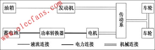
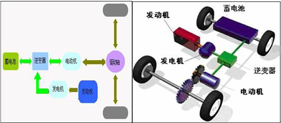
The hybrid system is divided into series, parallel, and hybrid. A series hybrid electric vehicle is mainly composed of an engine, a generator, a drive motor, and a battery pack. The engine is only used to generate electricity, the electric energy generated by the generator is supplied to the electric motor, and the electric motor drives the car to travel. Part of the power from the generator charges the battery to extend the mileage of the hybrid electric vehicle. In addition, the battery can also provide electric energy to the electric motor to drive the electric vehicle separately, so that the hybrid electric vehicle can run under zero pollution state. Please refer to Figure 2 for the series schematic diagram.
Parallel hybrid electric vehicles are mainly composed of components such as an engine, a generator/motor, and a battery pack. The parallel drive system can use the engine or the motor alone as the power source, or use the motor and the engine as the power source to drive the car at the same time. See Figure 3 for the parallel schematic.
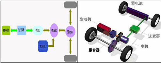
The hybrid hybrid electric vehicle is mainly composed of an engine, a generator, an electric motor, a planetary gear mechanism, and a battery pack. The hybrid drive method connects the engine, generator and motor through a planetary gear unit. Power is output from the engine to the planet carrier connected to it. The planet carrier transmits a portion of the torque to the generator and another portion to the motor and outputs it to the drive shaft. At this time, the vehicle is not in series or parallel, but between series and parallel, making full use of the advantages of the two driving methods. See Figure 4 for the schematic diagram of the mixing.

2: Hybrid vehicle battery control unit system setting requirements.
1: touch screen screen design requirements
This system uses WEINVIEWMT8070iH model touch screen, this model is 7" widescreen, 400MHz CPU. 128M large capacity Flash, can quickly respond to system commands.
The picture language requires switching between Chinese and English. The picture should have an animation effect. For example, the charging and discharging process of the battery should be synchronized with the actual and expressed by the animation effect.
The touch screen uses a 7-inch widescreen, and the main screen can visually indicate the operation of the user's fuel cell unit, as well as the operation of each battery and each battery and related parameters. For this battery management unit, there are a total of 10 groups, each group has 12 batteries, and it is required to display the voltage, current and temperature parameters of the 120 batteries. If the parameters are out of range, an alarm prompt must be issued.
2: Set the alarm voltage range:
When it is detected that the voltage of any string in the battery pack exceeds 3.00-3.65V, the submenu of the voltage and the warning triangle symbol should flash, enter the voltage submenu, the battery pack exceeding the standard should flash, and the corresponding battery pack is turned on. Page menu, the string that exceeds the standard flashes.
3: Set the alarm temperature range:
When it is detected that the temperature of any battery in the battery pack exceeds 70 degrees, the temperature submenu and the warning triangle symbol will flash, enter the temperature submenu, and the oversized battery pack will flash.
4: Calculation of battery capacity:
Calculation method: total current x total voltage x time = charge and discharge power; the touch screen is required to accurately display the charge and discharge data.
Three: the screen design of the touch screen system
1: Touch screen main monitor screen design
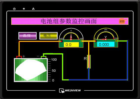
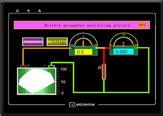
The main monitor screen of the touch screen is Chinese and English. As shown in the figure below, there is a battery symbol on the entire screen. The positive and negative labels can be used to display the current capacity of the battery. The first dial on the screen is an ammeter, which can display the charging and discharging of the battery unit; the second table is the voltmeter mainly showing the voltage after the battery pack is inverted. The temperature and voltage controls on the screen can be displayed as alarms and can be used as function keys for entering the next level of the directory.
2: Touch screen temperature monitoring screen design
Click the temperature button on the main screen to enter the battery module temperature monitoring screen. On this screen we can see the temperature of 10 groups of batteries. For each battery pack with 12 bars, the temperature sensor measures each 4 cells, so there are three temperature sensors in a group of batteries, which can be read through the touch screen. When the temperature abnormally exceeds the operating temperature of the battery, the corresponding battery icon will flash, which is convenient for the driver to view. The battery temperature monitoring screen is shown below.
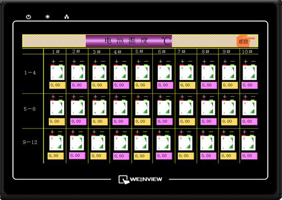
Battery temperature monitoring
3: Touch screen temperature and voltage picture design
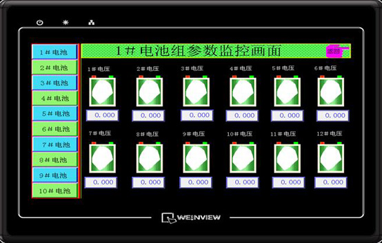
Click the voltage button on the main screen to enter the battery module voltage monitoring screen. In the screen, we can see the voltage of each battery in each battery. In the quick selection bar on the left side of the screen, you can switch between other battery packs and check the detailed voltage status of the battery pack.
In the battery unit, when one of the battery voltage ranges exceeds 3.00-3.65V, the corresponding battery icon will flash to perform related alarms; it is convenient for operators and drivers to query.
Four: communication between the touch screen and the controller
1: Development of communication protocol
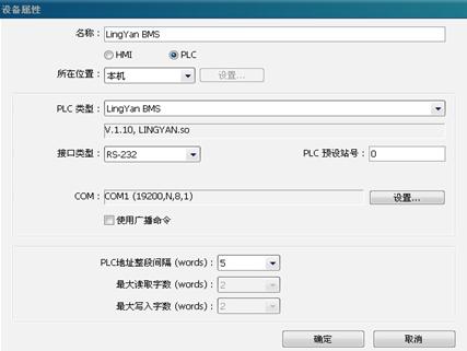
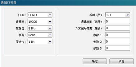
For the customer's controller is developed with a single-chip, so MT8070iH and its communication must have a communication protocol to communicate with the microcontroller. The communication parameters of the MCU have been set on the MCU side. Please refer to the following figure for the communication parameters of the touch screen.
2: Communication debugging and data testing
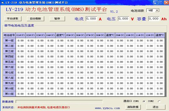
After the communication test is successful, we must conduct relevant tests on the correctness of the data. The test first needs to read the parameters of all the battery cells through the software of the single-chip microcomputer; then the data read by the touch screen and the single-chip microcomputer is consistent with the parameters read by the single-chip software. The software screen for reading data from the MCU is shown below. On the screen, we can read the parameters of each battery.
3: Test of the alarm system
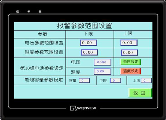
For the test of the alarm, we can set the alarm on the touch screen, the battery voltage alarm range, the battery temperature alarm range, and the battery capacity alarm range. This is convenient for the debugger to test whether the alarm is normal, because some of the battery's parameter voltage may be less than 3V during the debugging phase, so the alarm range is set by itself, which is more conducive to the communication test of the MT8070iH and the controller.
Five: Conclusion
The system adopts the control system composed of WEINVIEWMT8070iH touch screen and single chip microcomputer to be applied to the hybrid vehicle, and the fuel saving effect can reach 30%. The energy conversion effect is good, and the kinetic energy can be supplemented when the vehicle fuel system is insufficiently powered. When the brake is applied, the kinetic energy of the brake can be converted into electric energy and stored by the battery. The application of new energy vehicles is currently in its infancy, but this application not only meets the future development trend of fuel drive over-to-electric drive, but also greatly increases the environmental protection level of the automobile industry, which is of great significance to the improvement of human living environment.
SHENZHEN YINZHIGUAN DIGITAL TECHNOLOGY CO.,LTD , http://www.yzgmusiccrown.com